Inter-integrated circuit (I
2
C) interface RM0091
472/742 Doc ID 018940 Rev 1
23.4.4 Mode selection
The interface can operate in one of the four following modes:
● Slave transmitter
● Slave receiver
● Master transmitter
● Master receiver
By default, it operates in slave mode. The interface automatically switches from slave to
master when it generates a START condition, and from master to slave if an arbitration loss
or a STOP generation occurs, allowing multimaster capability.
Communication flow
In Master mode, the I
2
C interface initiates a data transfer and generates the clock signal. A
serial data transfer always begins with a START condition and ends with a STOP condition.
Both START and STOP conditions are generated in master mode by software.
In Slave mode, the interface is capable of recognizing its own addresses (7 or 10-bit), and
the General Call address. The General Call address detection can be enabled or disabled
by software. The reserved SMBus addresses can also be enabled by software.
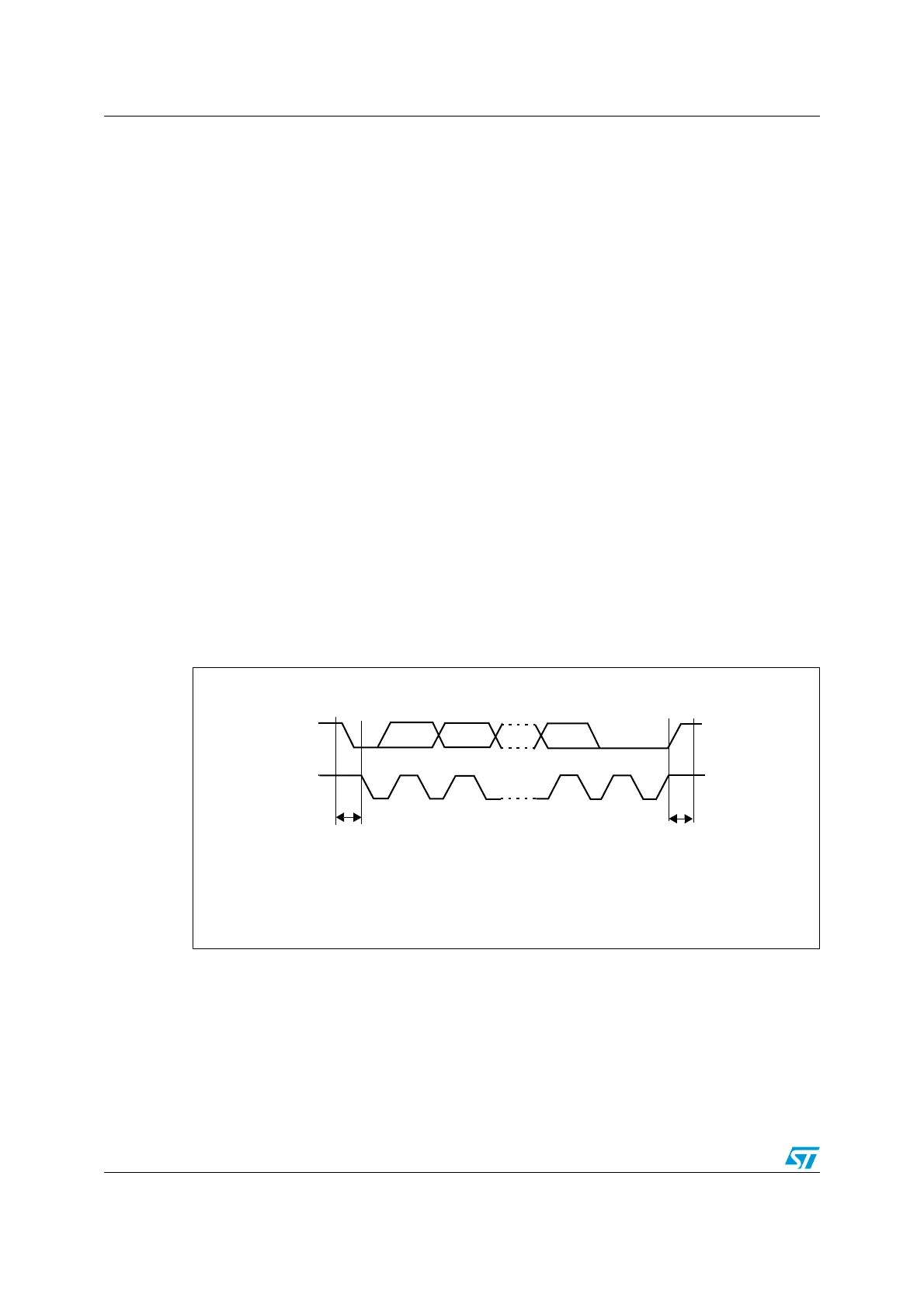
Data and addresses are transferred as 8-bit bytes, MSB first. The first byte(s) following the
START condition contain the address (one in 7-bit mode, two in 10-bit mode). The address
is always transmitted in Master mode.
A 9th clock pulse follows the 8 clock cycles of a byte transfer, during which the receiver must
send an acknowledge bit to the transmitter. Refer to the following figure.
Figure 197. I
2
C bus protocol
Acknowledge can be enabled or disabled by software. The I
2
C interface addresses can be
selected by software.
MS19854V1
SCL
SDA
12 8 9
MSB
ACK
Stop
Start
condition
condition