Serial peripheral interface / inter-IC sound (SPI/I2S) RM0091
650/742 Doc ID 018940 Rev 1
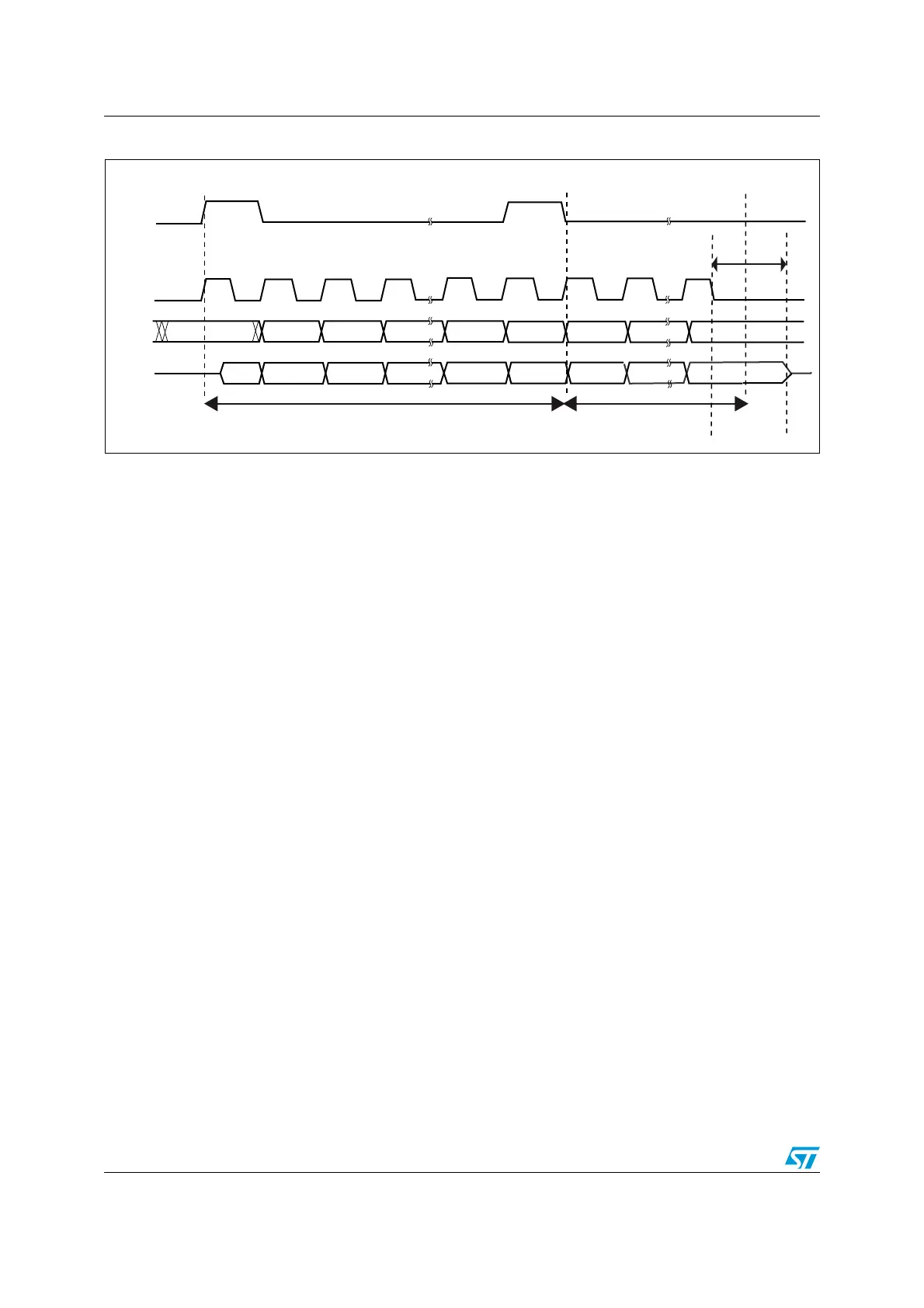
Figure 263. TI mode transfer
26.4.3 CRC calculation
Two separate CRC calculators are implemented in order to check the reliability of
transmitted and received data. The SPI offers CRC8 or CRC16 calculation independently of
the frame data length, which can be fixed to 8-bit or 16-bit. For all the other data frame
lengths, no CRC is available.
CRC principle
CRC calculation is enabled by setting the CRCEN bit in the SPIx_CR1 register before the
SPI is enabled (SPE = 1). The CRC value is calculated using an odd programmable
polynomial on each bit. The calculation is processed on the sampling clock edge defined by
the CPHA and CPOL bits in the SPIx_CR1 register. The calculated CRC value is checked
automatically at the end of the data block as well as for transfer managed by CPU or by the
DMA. When a mismatch is detected between the CRC calculated internally on the received
data and the CRC sent by the transmitter, a CRCERR flag is set to indicate a data
corruption error. The right procedure for handling the CRC calculation depends on the SPI
configuration and the chosen transfer management.
Note: The polynomial value should only be odd. No even values are supported.
MS19835V1
MSBOUT
MOSI
NSS
SCK
trigger
sampling
trigger
sampling
t
rigger
sampling
DONTCARE LSBOUT
MISO
1 or 0 MSBIN
LSBIN
MSBOUT LSBOUT
MSBIN
LSBIN
FRAME 1
FRAME 2
t
RELEASE