RM0091 Serial peripheral interface / inter-IC sound (SPI/I2S)
Doc ID 018940 Rev 1 661/742
Figure 282. Audio sampling frequency definition
When the master mode is configured, a specific action needs to be taken to properly
program the linear divider in order to communicate with the desired audio frequency.
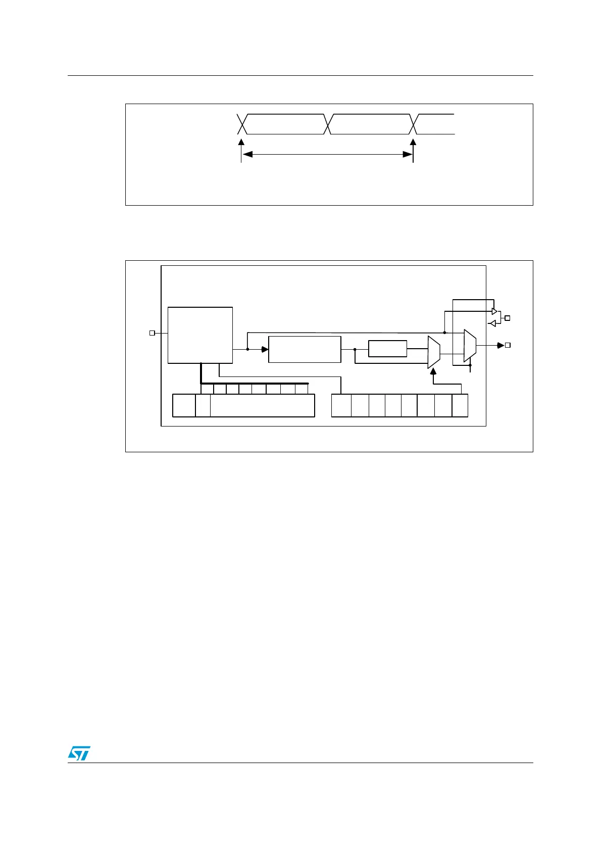
Figure 283. I
2
S clock generator architecture
1. Where x can be 2 or 3.
Figure 282 presents the communication clock architecture. The I2Sx clock is always the
system clock.
The audio sampling frequency may be 192 KHz, 96 kHz, 48 kHz, 44.1 kHz, 32 kHz, 22.05
kHz, 16 kHz, 11.025 kHz or 8 kHz (or any other value within this range). In order to reach
the desired frequency, the linear divider needs to be programmed according to the formulas
below:
When the master clock is generated (MCKOE in the SPIx_I2SPR register is set):
f
S
= I2SxCLK / [(16*2)*((2*I2SDIV)+ODD)*8)] when the channel frame is 16-bit wide
f
S
= I2SxCLK / [(32*2)*((2*I2SDIV)+ODD)*4)] when the channel frame is 32-bit wide
When the master clock is disabled (MCKOE bit cleared):
f
S
= I2SxCLK / [(16*2)*((2*I2SDIV)+ODD))] when the channel frame is 16-bit wide
f
S
= I2SxCLK / [(32*2)*((2*I2SDIV)+ODD))] when the channel frame is 32-bit wide
Tabl e 92 provides example precision values for different clock configurations.
Note: Other configurations are possible that allow optimum clock precision.
MS30108V1
16-or 32-bit
left channel
16-or 32-bit
right channel
32- or 64-bits
sampling point sampling point
F
S
F
S
: audio sampling frequency
MS30109V1
MCKOE
ODD
8-bit linear
divider +
reshaping stage
Divider by 4
Div2
I²SDIV[7:0]
I²SMOD
CHLEN
0
1
0
1
MCKOE
CK
MCK
I²SxCLK