RM0091 Universal synchronous asynchronous receiver transmitter (USART)
Doc ID 018940 Rev 1 611/742
25.7 USART registers
Refer to Section 1.1 on page 34 for a list of abbreviations used in register descriptions.
25.7.1 Control register 1 (USART_CR1)
Address offset: 0x00
Reset value: 0x0000
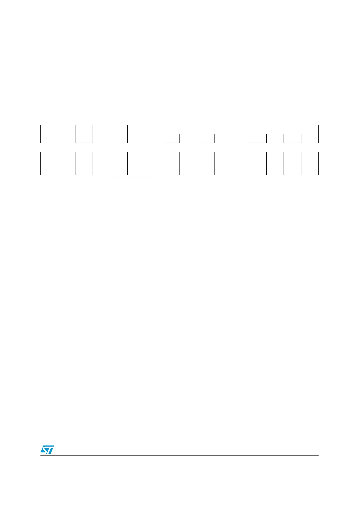
31 30 29 28 27 26 25 24 23 22 21 20 19 18 17 16
Res Res Res Res EOBIE RTOIE DEAT[4:0] DEDT[4:0]
rw rw rw rw rw rw rw rw rw rw rw rw
1514131211109876543210
OVER
8
CMIE MME M WAKE PCE PS PEIE TXEIE TCIE
RXNEI
E
IDLEIE TE RE UESM UE
rw rw rw rw rw rw rw rw rw rw rw rw rw rw rw rw
Bits 31:28 Reserved, must be kept at reset value
Bit 27 EOBIE: End of Block interrupt enable
This bit is set and cleared by software.
0: Interrupt is inhibited
1: A USART interrupt is generated when the EOBF flag is set in the USART_ISR register
Note: If the USART does not support Smartcard mode, this bit is reserved and forced by
hardware to ‘0’. Please refer to Section 25.4: USART implementation on page 573.
Bit 26 RTOIE: Receiver timeout interrupt enable
This bit is set and cleared by software.
0: Interrupt is inhibited
1: A USART interrupt is generated when the RTOF bit is set in the USART_ISR register.
Note: If the USART does not support the Receiver timeout feature, this bit is reserved and
forced by hardware to ‘0’. Section 25.4: USART implementation on page 573.
Bits 25:21 DEAT[4:0]: Driver Enable assertion time
This 5-bit value defines the time between the activation of the DE (Driver Enable) signal and
the beginning of the start bit. It is expressed in sample time units (1/8 or 1/16 bit time,
depending on the oversampling rate)
Note: If the Driver Enable feature is not supported, this bit is reserved and must be kept
cleared. Please refer to Section 25.4: USART implementation on page 573.
This bit field can only be written when the USART is disabled (UE=0).
Bits 20:16 DEDT[4:0]: Driver Enable deassertion time
This 5-bit value defines the time between the end of the last stop bit, in a transmitted message,
and the de-activation of the DE (Driver Enable) signal. It is expressed in sample time units (1/8
or 1/16 bit time, depending on the oversampling rate).
If the USART_TDR register is written during the DEDT time, the new data is transmitted only
when the DEDT and DEAT times have both elapsed.
Note: If the Driver Enable feature is not supported, this bit is reserved and must be kept
cleared. Please refer to Section 25.4: USART implementation on page 573.
This bit field can only be written when the USART is disabled (UE=0).