RM0091 Analog-to-digital converter (ADC)
Doc ID 018940 Rev 1 171/742
12.4 ADC functional description
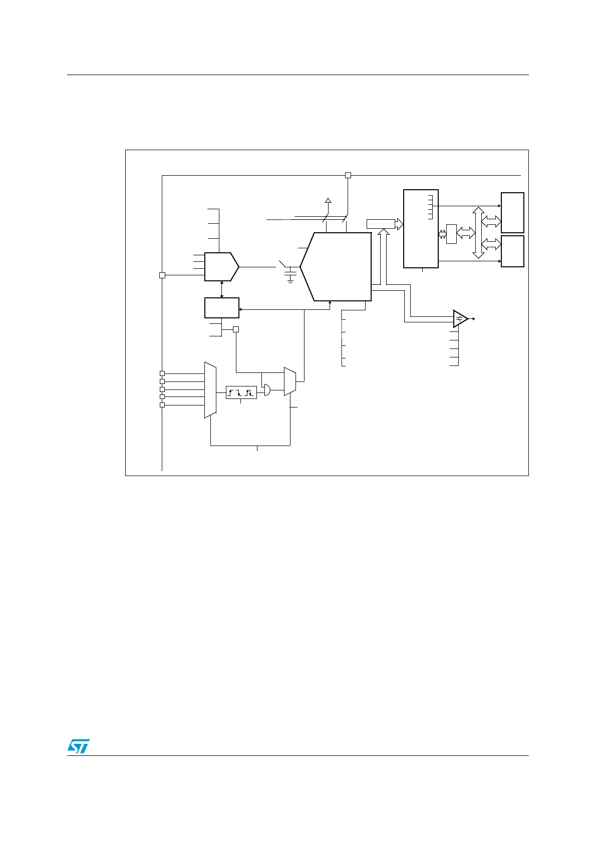
Figure 22 shows the ADC block diagram and Tabl e 3 0 gives the ADC pin description.
Figure 22. ADC block diagram
12.4.1 Calibration (ADCAL)
The ADC has a calibration feature. During the procedure, the ADC calculates a calibration
factor which is internally applied to the ADC until the next ADC power-off. The application
must not use the ADC during calibration and must wait until it is complete.
Calibration should be performed before starting A/D conversion. It removes the offset error
which may vary from chip to chip due to process variation.
The calibration is initiated by software by setting bit ADCAL=1. Calibration can only be
initiated when the ADC is disabled (when ADEN=0). ADCAL bit stays at 1 during all the
calibration sequence. It is then cleared by hardware as soon the calibration completes. After
this, the calibration factor can be read from the ADC_DR register (from bits 6 to 0).
The calibration factor is kept if the ADC is disabled (ADEN=0). However, if the ADC is
disabled for extended periods, then it is recommended that a new calibration cycle is run
before re-enabling the ADC.
The calibration factor is lost each time power is removed from the ADC (for example when
the product enters STANDBY or VBAT mode).
V
REF
T
S
V
BAT
TIM1_TRGO
TIM1_CC4
TIM2_TRGO
TIM3_TRGO
TIM15_TRGO
CONT
singe/cont
Input
Selection &
Scan Control
SMP[2:0]
sampling time
Start & Stop
Control
ADC_IN[15:0]
analog input
channels
AUTDLY
auto-delayed conv
ADSTP
stop conv
ADSTART
s/w trigger
EXTEN[1:0]
trigger enable
and edge selection
h/w
trigger
EXTSEL[2:0]
trigger selection
ADCAL
self calibration
AWDx
SAR ADC
Vin
start
Supply and
ALIGN
left/right
RES[1:0]
12,10,8,bts
OVRMOD
overrun mode
APB
interface
DMAEN
DMA request
ADC Interrupt
CPU
DMA
master
master
slave
A
H
B
IRQ
CH_SEL[18:0]
SCANDIR
DMACFG
AREADY
EOSMP
EOC
EOSEQ
OVR
AWD
AWDxEN
Analog
AWDxSGL
AWDCHx[4:0]
LTx[ 11:0 ]
HTx[11:0]
JOFFSETx[11:0]
JOFFSETx_CH[11:0]
CONVERTED DATA
DATA[11:0]
DISCEN
discontinuous
watchdog
AHB
TO
APB
mode
up/down
AUTOFF
auto-off mode
ADEN/ADDIS
Analog Supply
2.4V to 3.6
V
DDA
≥ V
DD
reference