Universal synchronous asynchronous receiver transmitter (USART) RM0091
580/742 Doc ID 018940 Rev 1
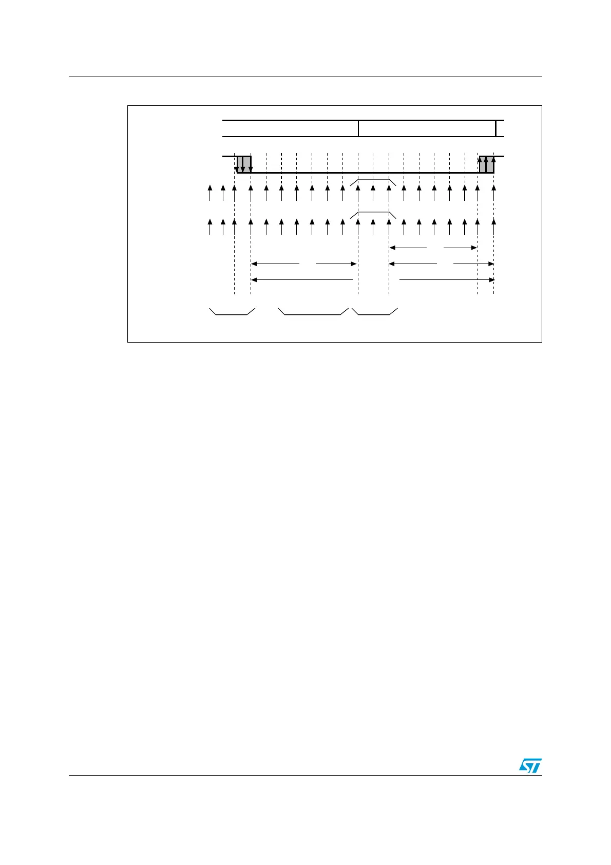
Figure 232. Start bit detection when oversampling by 16 or 8
Note: If the sequence is not complete, the start bit detection aborts and the receiver returns to the
idle state (no flag is set), where it waits for a falling edge.
The start bit is confirmed (RXNE flag set, interrupt generated if RXNEIE=1) if the 3 sampled
bits are at 0 (first sampling on the 3rd, 5th and 7th bits finds the 3 bits at 0 and second
sampling on the 8th, 9th and 10th bits also finds the 3 bits at 0).
The start bit is validated (RXNE flag set, interrupt generated if RXNEIE=1) but the NE noise
flag is set if, for both samplings, at least 2 out of the 3 sampled bits are at 0 (sampling on the
3rd, 5th and 7th bits and sampling on the 8th, 9th and 10th bits). If this condition is not met,
the start detection aborts and the receiver returns to the idle state (no flag is set).
If, for one of the samplings (sampling on the 3rd, 5th and 7th bits or sampling on the 8th, 9th
and 10th bits), 2 out of the 3 bits are found at 0, the start bit is validated but the NE noise
flag bit is set.
Character reception
During an USART reception, data shifts in least significant bit first (default configuration)
through the RX pin. In this mode, the USART_RDR register consists of a buffer (RDR)
between the internal bus and the received shift register.
Procedure:
1. Program the M bit in USART_CR1 to define the word length.
2. Select the desired baud rate using the baud rate register USART_BRR
3. Program the number of stop bits in USART_CR2.
4. Enable the USART by writing the UE bit in USART_CR1 register to 1.
5. Select DMA enable (DMAR) in USART_CR3 if multibuffer communication is to take
place. Configure the DMA register as explained in multibuffer communication. STEP 3
6. Set the RE bit USART_CR1. This enables the receiver which begins searching for a
start bit.
RX line
sampled values
Idle Start bitRX state
Real
sample
clock
Ideal
sample
clock
010X0X0000XXXXXX
Conditions
to validate
the start bit
At least 2 bits
out of 3 at 0
At least 2 bits
out of 3 at 0
Falling edge
detection
11
1 2 3 4 5 6 7 8 9 10 11 12 13 14 15 16
X X X X X X X X 9 10 111213141516
6/16
7/16
One-bit time
7/16
X
ai15471