RM0091 System configuration controller (SYSCFG)
Doc ID 018940 Rev 1 135/742
9 System configuration controller (SYSCFG)
The devices feature a set of configuration registers. The main purposes of the system
configuration controller are the following:
● Enabling/disabling I
2
C Fast Mode Plus on some IO ports
● Remapping some DMA trigger sources from TIM16 and TIM17, USART1, and ADC to
different DMA channels
● Remapping the memory located at the beginning of the code area
● Managing the external interrupt line connection to the GPIOs
● Managing robustness feature
9.1 SYSCFG registers
9.1.1 SYSCFG configuration register 1 (SYSCFG_CFGR1)
This register is used for specific configurations on memory remap.
Two bits are used to configure the type of memory accessible at address 0x0000 0000.
These bits are used to select the physical remap by software and so, bypass the hardware
BOOT selection.
After reset these bits take the value selected by the BOOT pin (BOOT0) and by the option bit
(nBOOT1).
Address offset: 0x00
Reset value: 0x0000 000X (X is the memory mode selected by the BOOT0 pin and nBOOT1
option bit)
)
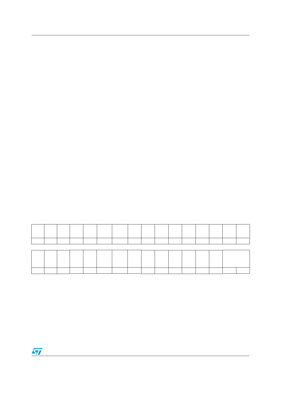
31 30 29 28 27 26 25 24 23 22 21 20 19 18 17 16
Res. Res. Res. Res. Res. Res. Res. Res. Res. Res. Res. Res.
I2C_
PB9_
FM+
I2C_
PB8_
FM+
I2C_
PB7_
FM+
I2C_
PB6_
FM+
rw rw rw rw
15 14 13 12 11 10 9 8 7 6 5 4 3 2 1 0
Res. Res. Res.
TIM17_
DMA_
RMP
TIM16_
DMA_
RMP
USART1
_RX_
DMA_
RMP
USART1
_TX_
DMA_
RMP
ADC_
DMA_
RMP
Res. Res. Res. Res. Res. Res.MEM_MODE
rw rw rw rw rw rw rw
Bits 31:20 Reserved, must be kept at reset value.
Bits 19:16 I2C_PBx_FM+: Fast Mode Plus (FM+) driving capability activation bits.
These bits are set and cleared by software. Each bit enables I
2
C FM+ mode for PB6, PB7,
PB8, and PB9 I/Os.
0: PBx pin operates in standard mode.
1: I
2
C FM+ mode enabled on PBx pin, and the Speed control is bypassed.
Bits 15:13 Reserved, must be kept at reset value.