Reset and clock control (RCC) RM0091
94/742 Doc ID 018940 Rev 1
7.4.2 Clock configuration register (RCC_CFGR)
Address offset: 0x04
Reset value: 0x0000 0000
Access: 0 ≤ wait state ≤ 2, word, half-word and byte access
1 or 2 wait states inserted only if the access occurs during clock source switch.
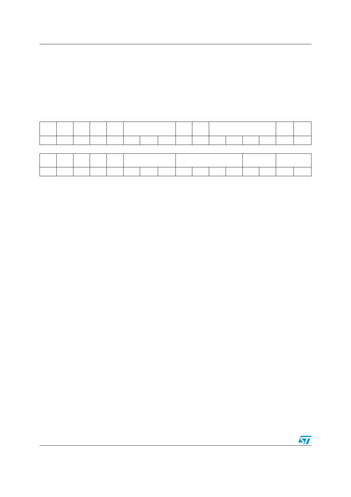
31 30 29 28 27 26 25 24 23 22 21 20 19 18 17 16
Res Res Res Res Res MCO[2:0] Res Res PLLMUL[3:0]
PLL
XTPRE
PLL
SRC
rw rw rw rw rw rw rw rw rw
15 14 13 12 11 10 9 8 7 6 5 4 3 2 1 0
Res
ADCP
RE
Res Res Res PPRE[2:0] HPRE[3:0] SWS[1:0] SW[1:0]
rw rw rw rw rw rw rw rw r r rw rw
Bits 31:27 Reserved, must be kept at reset value.
Bits 26:24 MCO: Microcontroller clock output
Set and cleared by software.
000: MCO output disabled, no clock on MCO
001: Reserved
010: Reserved
011: HSI14 clock selected
100: System clock (SYSCLK) selected
101: HSI clock selected
110: HSE clock selected
111: PLL clock divided by 2 selected
Note: This clock output may have some truncated cycles at startup or during MCO clock
source switching.
Bits 23:22 Reserved, must be kept at reset value.