General-purpose timer (TIM14) RM0091
364/742 Doc ID 018940 Rev 1
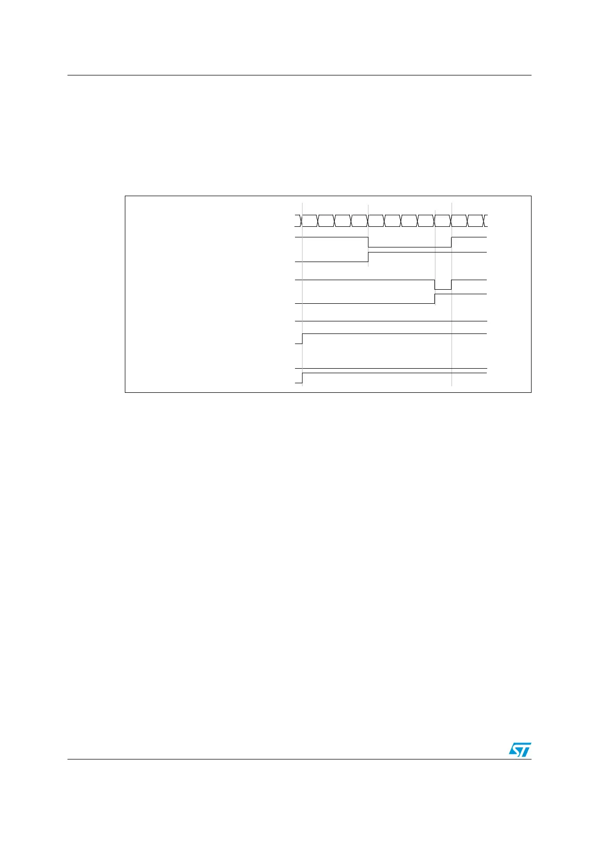
PWM edge-aligned mode
In the following example, we consider PWM mode 1. The reference PWM signal OCxREF is
high as long as TIMx_CNT < TIMx_CCRx else it becomes low. If the compare value in
TIMx_CCRx is greater than the auto-reload value (in TIMx_ARR) then OCxREF is held at
‘1’. If the compare value is 0 then OCxRef is held at ‘0’. Figure 151 shows some edge-
aligned PWM waveforms in an example where TIMx_ARR=8.
Figure 151. Edge-aligned PWM waveforms (ARR=8)
17.3.9 Debug mode
When the microcontroller enters debug mode (Cortex™-M0 core halted), the TIMx counter
either continues to work normally or stops, depending on DBG_TIMx_STOP configuration
bit in DBG module. .
Counter register
‘
0
1234567801
‘
OCXREF
CCxIF
OCXREF
CCxIF
OCXREF
CCxIF
OCXREF
CCxIF
CCRx=4
CCRx=8
CCRx>8
CCRx=0