RM0091 Universal synchronous asynchronous receiver transmitter (USART)
Doc ID 018940 Rev 1 573/742
25.4 USART implementation
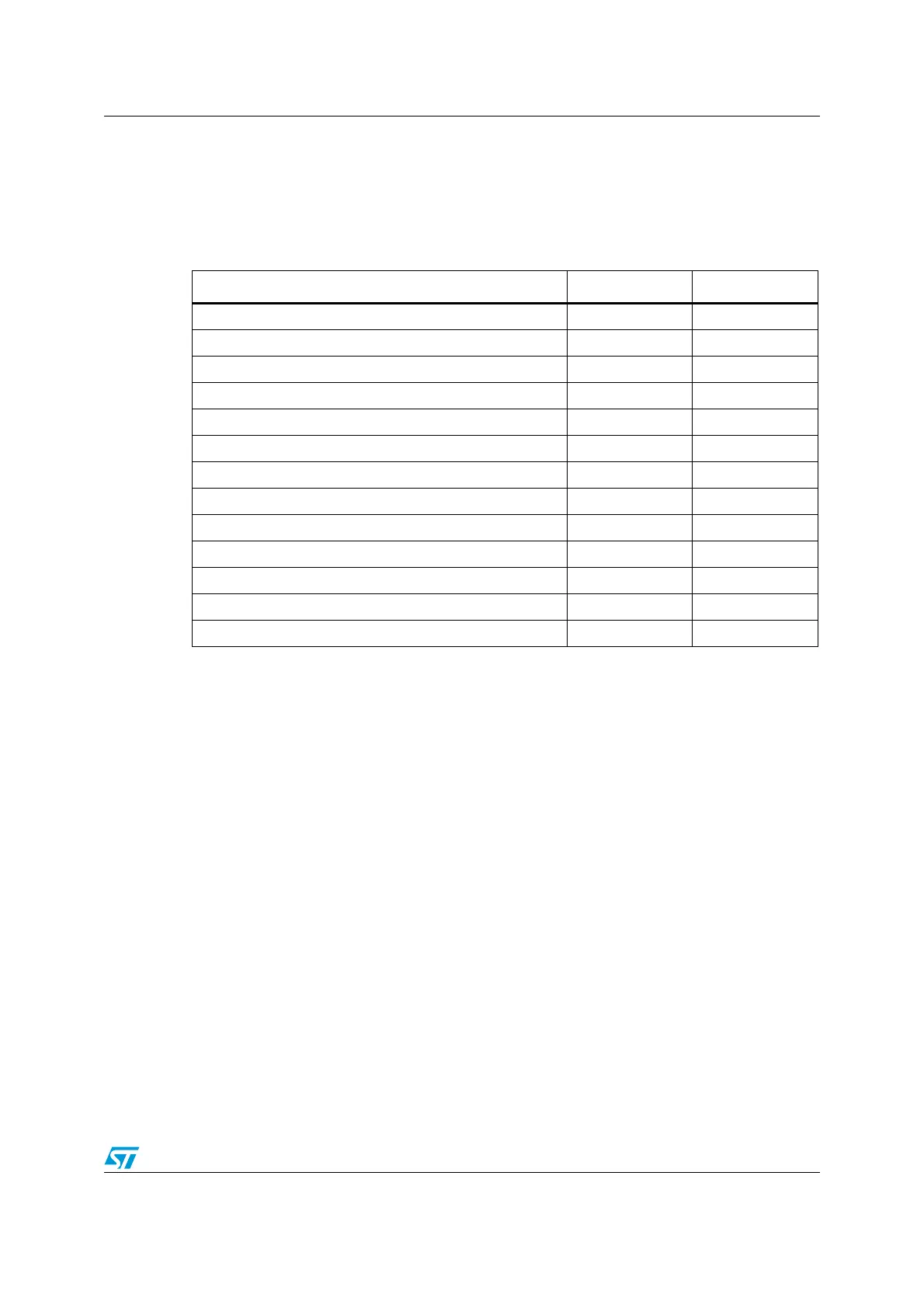
This manual describes the full set of features implemented in USART1. USART2 supports a
smaller set of features, but is otherwise identical to USART1. The differences are listed in
the following table.
25.5 USART functional description
Any USART bidirectional communication requires a minimum of two pins: Receive Data In
(RX) and Transmit Data Out (TX):
RX: Receive Data Input is the serial data input. Oversampling techniques are used for data
recovery by discriminating between valid incoming data and noise.
TX: Transmit Data Output. When the transmitter is disabled, the output pin returns to its I/O
port configuration. When the transmitter is enabled and nothing is to be transmitted, the TX
pin is at high level. In single-wire and Smartcard modes, this I/O is used to transmit and
receive the data.
Table 83. STM32F05xxx USART features
USART modes/features
(1)
1. X = supported.
USART1 USART2
Hardware flow control for modem X X
Continuous communication using DMA X X
Multiprocessor communication X X
Synchronous mode X X
Smartcard mode X
Single-wire half-duplex communication X X
IrDA SIR ENDEC block X
LIN mode X
Dual clock domain and wakeup from Stop mode X
Receiver timeout interrupt X
Modbus communication X
Auto baud rate detection X
Driver Enable X X