RM0091 General-purpose timer (TIM14)
Doc ID 018940 Rev 1 355/742
Note that the counter starts counting 1 clock cycle after setting the CEN bit in the TIMx_CR1
register.
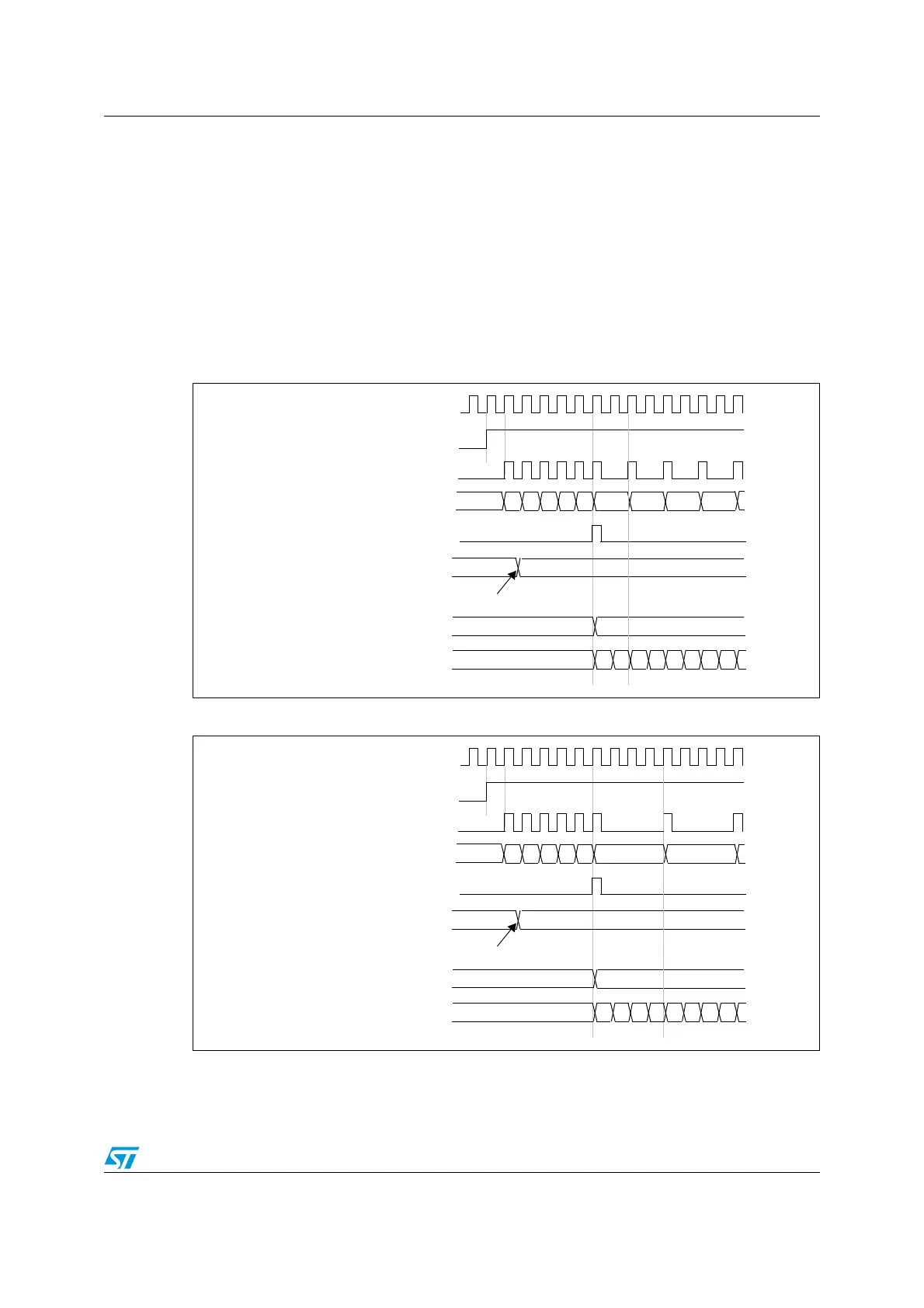
Prescaler description
The prescaler can divide the counter clock frequency by any factor between 1 and 65536. It
is based on a 16-bit counter controlled through a 16-bit register (in the TIMx_PSC register).
It can be changed on the fly as this control register is buffered. The new prescaler ratio is
taken into account at the next update event.
Figure 139 and Figure 140 give some examples of the counter behavior when the prescaler
ratio is changed on the fly.
Figure 138. Counter timing diagram with prescaler division change from 1 to 2
Figure 139. Counter timing diagram with prescaler division change from 1 to 4
CK_PSC
00
CEN
Timer clock = CK_CNT
Counter register
Update event (UEV)
0
F9 FA FB FCF7
Prescaler control register
01
Write a new value in TIMx_PSC
01 02 03
Prescaler buffer
01
Prescaler counter
0
1 0 1 0 1 0 1
F8
CK_PSC
00
CEN
Timer clock = CK_CNT
Counter register
Update event (UEV)
0
F9 FA FB FCF7
Prescaler control register
03
Write a new value in TIMx_PSC
Prescaler buffer
03
Prescaler counter
0
1 2 3 0 1 2 3
F8 01