RM0091 Universal synchronous asynchronous receiver transmitter (USART)
Doc ID 018940 Rev 1 621/742
25.7.4 Baud rate register (USART_BRR)
This register can only be written when the USART is disabled (UE=0). It may be automatically updated
by hardware in auto baud rate detection mode.
Address offset: 0x0C
Reset value: 0x0000
Bit 2 IRLP: IrDA low-power
This bit is used for selecting between normal and low-power IrDA modes
0: Normal mode
1: Low-power mode
This bit can only be written when the USART is disabled (UE=0).
Note: If IrDA mode is not supported, this bit is reserved and forced by hardware to ‘0’. Please
refer to Section 25.4: USART implementation on page 573.
Bit 1 IREN: IrDA mode enable
This bit is set and cleared by software.
0: IrDA disabled
1: IrDA enabled
This bit can only be written when the USART is disabled (UE=0).
Note: If IrDA mode is not supported, this bit is reserved and forced by hardware to ‘0’. Please
refer to Section 25.4: USART implementation on page 573.
Bit 0 EIE: Error interrupt enable
Error Interrupt Enable Bit is required to enable interrupt generation in case of a framing
error, overrun error or noise flag (FE=1 or ORE=1 or NF=1 in the USART_ISR register).
0: Interrupt is inhibited
1: An interrupt is generated when FE=1 or ORE=1 or NF=1 in the USART_ISR register.
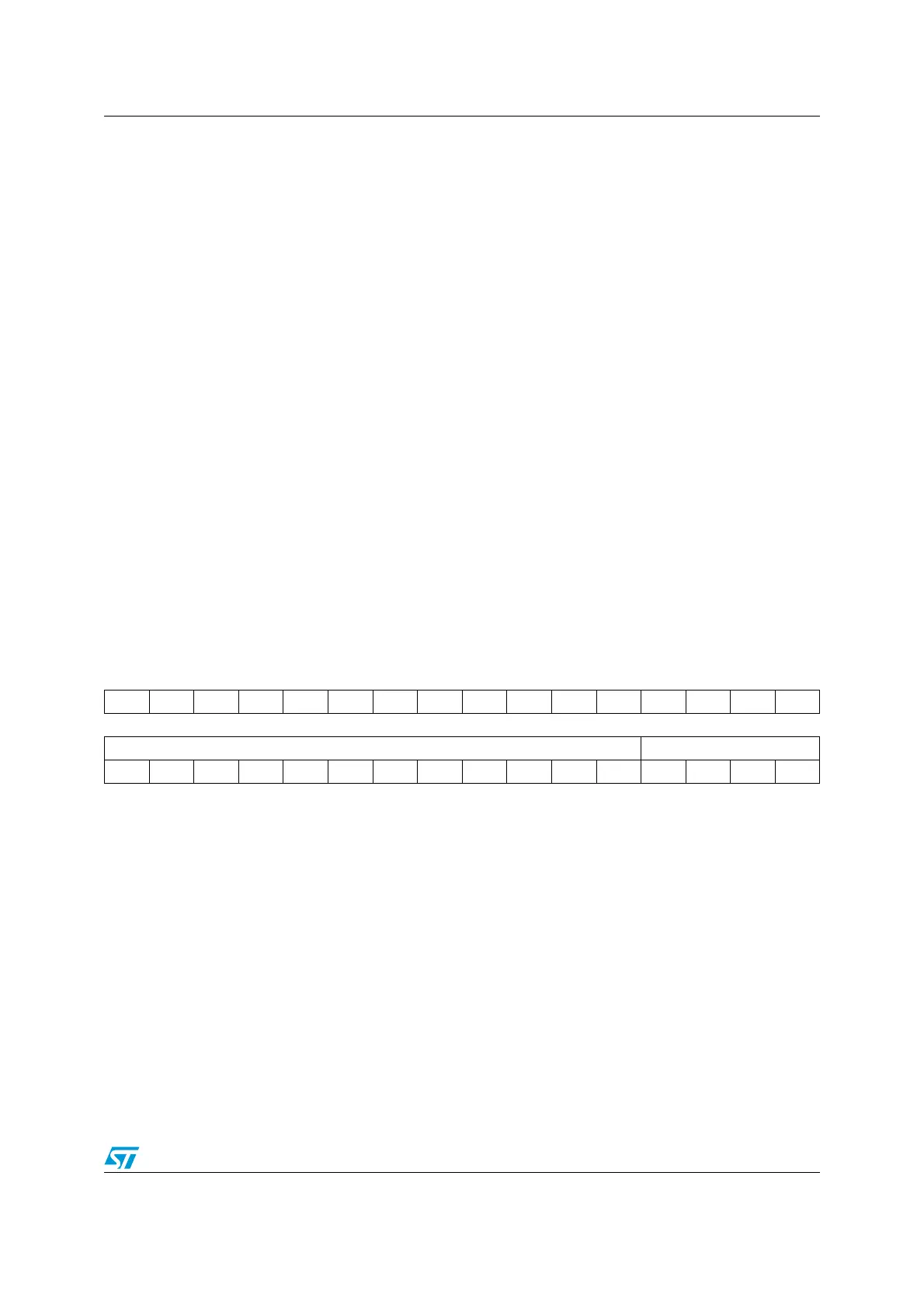
31 30 29 28 27 26 25 24 23 22 21 20 19 18 17 16
Res Res Res Res Res Res Res Res Res Res Res Res Res Res Res Res
1514131211109876543210
BRR[15:4] BRR[3:0]
rw rw rw rw rw rw rw rw rw rw rw rw rw rw rw rw
Bits 31:16 Reserved, must be kept at reset value.
Bits 15:4 BRR[15:4]
BRR[15:4] = USARTDIV[15:4]
Bits 3:0 BRR[3:0]
When OVER8 = 0, BRR [3:0] = USARTDIV [3:0]
When OVER8 = 1, BRR [2:0] = USARTDIV [3:0] shifted 1 bit to the right. BRR [3] must be
kept cleared.