RM0091 Power control (PWR)
Doc ID 018940 Rev 1 79/742
6.4.2 Power control/status register (PWR_CSR)
Address offset: 0x04
Reset value: 0x0000 0000 (not reset by wakeup from Standby mode)
Additional APB cycles are needed to read this register versus a standard APB read.
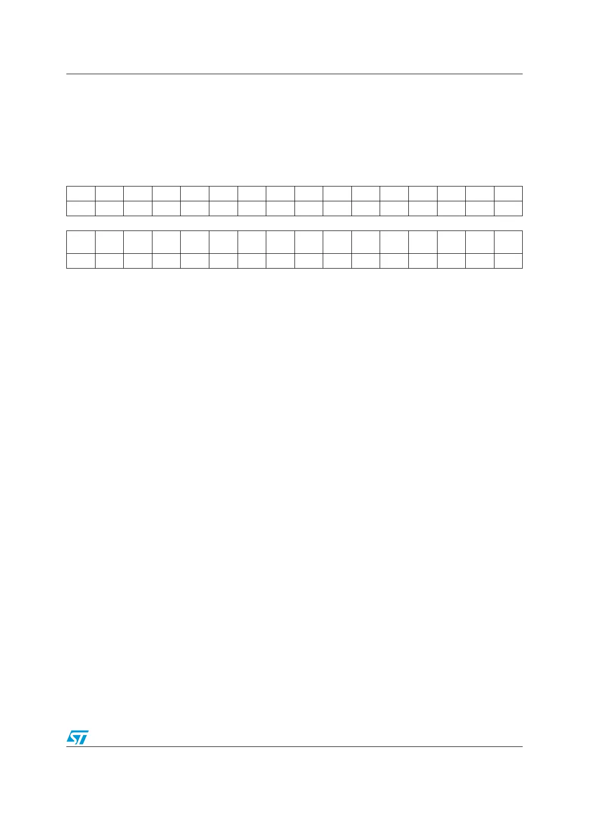
31 30 29 28 27 26 25 24 23 22 21 20 19 18 17 16
Res Res Res Res Res Res Res Res Res Res Res Res Res Res Res Res
1514131211109876543210
Res Res Res Res Res Res
EWUP
2
EWUP
1
Res Res Res Res Res PVDO SBF WUF
rw rw r r r
Bits 31:10 Reserved, must be kept at reset value.
Bit 9 EWUP2: Enable WKUP2 pin
This bit is set and cleared by software.
0: WKUP2 pin is used for general purpose I/O. An event on the WKUP2 pin does not wakeup
the device from Standby mode.
1: WKUP2 pin is used for wakeup from Standby mode and forced in input pull down
configuration (rising edge on WKUP1 pin wakes-up the system from Standby mode).
Note: This bit is reset by a system Reset.
Bit 8 EWUP1: Enable WKUP1 pin
This bit is set and cleared by software.
0: WKUP1 pin is used for general purpose I/O. An event on the WKUP1 pin does not wakeup
the device from Standby mode.
1: WKUP1 pin is used for wakeup from Standby mode and forced in input pull down
configuration (rising edge on WKUP1 pin wakes-up the system from Standby mode).
Note: This bit is reset by a system Reset.
Bits 7:3 Reserved, must be kept at reset value.
Bit 2 PVDO: PVD output
This bit is set and cleared by hardware. It is valid only if PVD is enabled by the PVDE bit.
0: V
DD
is lower than the PVD threshold selected with the PLS[2:0] bits.
1: V
DD
is higher than the PVD threshold selected with the PLS[2:0] bits.
Notes:
1. The PVD is stopped by Standby mode. For this reason, this bit is equal to 0 after Standby
or reset until the PVDE bit is set.
2. Once the PVD is enabled and configured in the PWR_CR register, PVDO can be used to
generate an interrupt through the External Interrupt controller.
Bit 1 SBF: Standby flag
This bit is set by hardware when the device enters Standby mode and it is cleared only by a
POR/PDR (power on reset/power down reset) or by setting the CSBF bit in the Power control
register (PWR_CR)
0: Device has not been in Standby mode
1: Device has been in Standby mode