RM0091 Inter-integrated circuit (I
2
C) interface
Doc ID 018940 Rev 1 473/742
23.4.5 I
2
C initialization
Enabling and disabling the peripheral
The I2C peripheral clock must be configured and enabled in the clock controller (refer to the
RCC Clocks section.
Then the I2C can be enabled by setting the PE bit in the I2Cx_CR1 register.
When the I2C is disabled (PE=0), the I2C performs a software reset: I2C lines (SDA and
SCL) are released. The internal state machines are reset, and all communication control
bits and status bits are put back to their reset value. The impacted bits are the same as
those listed in Section 23.4.6: Software reset.
Noise filters
Before you enable the I2C peripheral by setting the PE bit in I2Cx_CR1 register, you must
configure the noise filters, if needed. By default, an analog noise filter is present on the SDA
and SCL inputs. This analog filter is compliant with the I2C specification which requires the
suppression of spikes with a pulse width up to 50 ns in Fast Mode and Fast Mode Plus. You
can disable this analog filter by setting the ANFOFF bit, and/or select a digital filter by
configuring the DNF[3:0] bit in the I2Cx_CR1 register.
The digital filter is able to suppress spikes with a programmable length of 1 to 15 I2CCLK
periods.
Caution: Changing the filter configuration is not allowed when the I2C is enabled.
I2C timings
The timings must be configured in order to guarantee a correct data hold and setup time,
used in master and slave modes. This is done by programming the PRESC[3:0],
SCLDEL[3:0] and SDADEL[3:0] bits in the I2Cx_TIMINGR register.
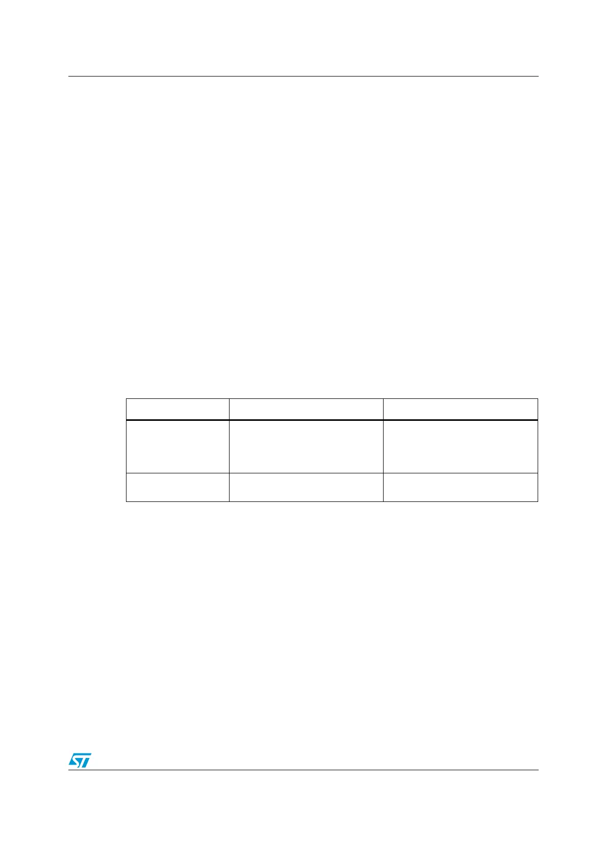
Table 63. Comparison of analog vs. digital filters
Analog filter Digital filter
Benefits Available in Stop mode
1. Programmable length: extra
filtering capability vs. standard
requirements
2. Stable length
Drawbacks
Variation vs. temperature, voltage,
process
Disabled when Wakeup form Stop
mode is enabled