HDMI-CEC controller (HDMI-CEC) RM0091
700/742 Doc ID 018940 Rev 1
28.3 HDMI-CEC functional description
28.3.1 HDMI-CEC pin
The CEC bus consists of a single bidirectional line that is used to transfer data in and out of
the device. It is connected to a +3.3 V supply voltage via a 27 kΩ pull-up resistor. The output
stage of the device must have an open-drain or open-collector to allow a wired-and
connection.
The HDMI-CEC controller manages the CEC bidirectional line as an alternate function of a
standard GPI/O, assuming that it is configured as Alternate Function Open Drain. The 27 kΩ
pull-up must be added externally to the STM32.
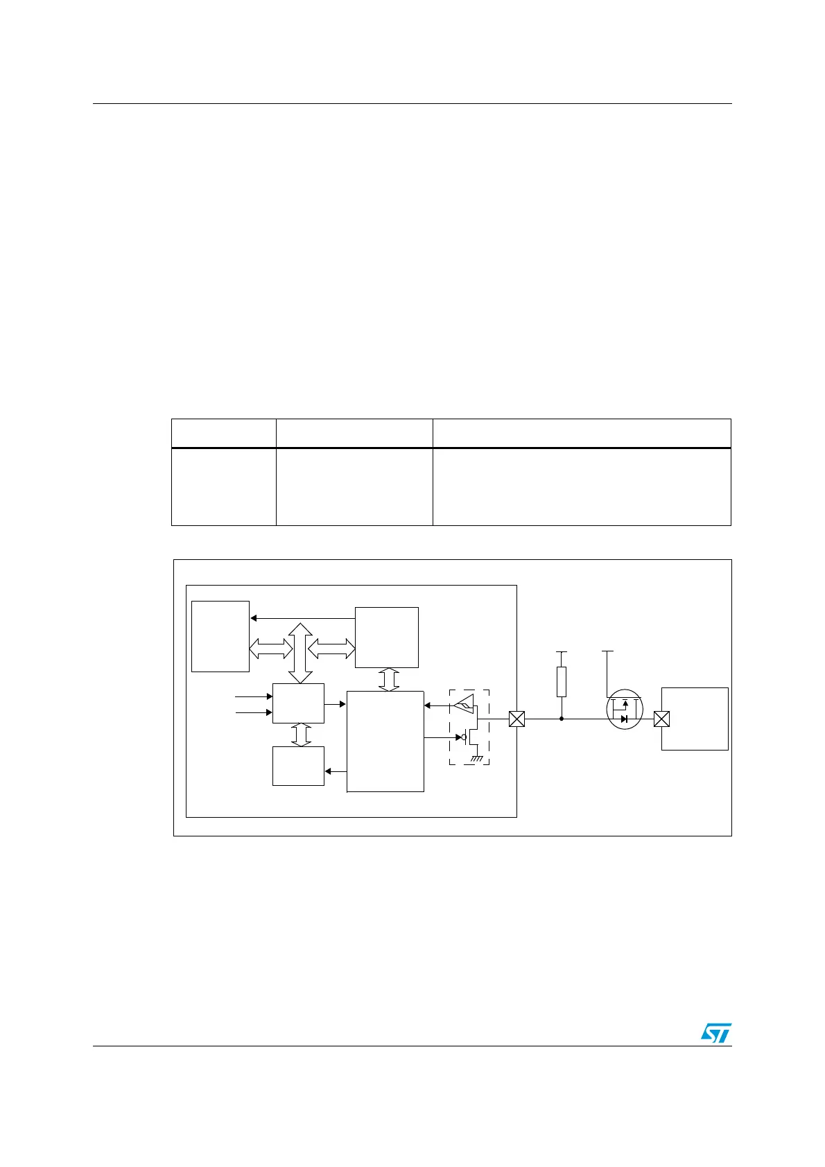
To not interfere with the CEC bus when the application power is removed, it is mandatory to
isolate the CEC pin from the bus in such conditions. This could be done by using a MOS
transistor, as shown on Figure 289.
Figure 289. Block diagram
1. GPI/O configured as output open-drain alternate function
2. When configured as output open-drain alternate function, the schmit trigger is still activated.
Table 102. HDMI pin
Name Signal type Remarks
CEC bidirectional
two states:
1 = high impedance
0 = low impedance
A 27 kΩ must be added externally.
STM32
CEC interrupt
HDMI_CEC
APB
Cortex-M0
Remote
27 N˖
3.3V
CEC
PAD(*)
device
HSI/255
LSE
RCC
32 kHz
CEC
AHB
Event
control
CEC
CEC
ITF
Tx
Rxclk
Kernel
Wake-int
controller
MS19885V2
G
3.3V
S
D
CEC line