General-purpose timers (TIM2 and TIM3) RM0091
328/742 Doc ID 018940 Rev 1
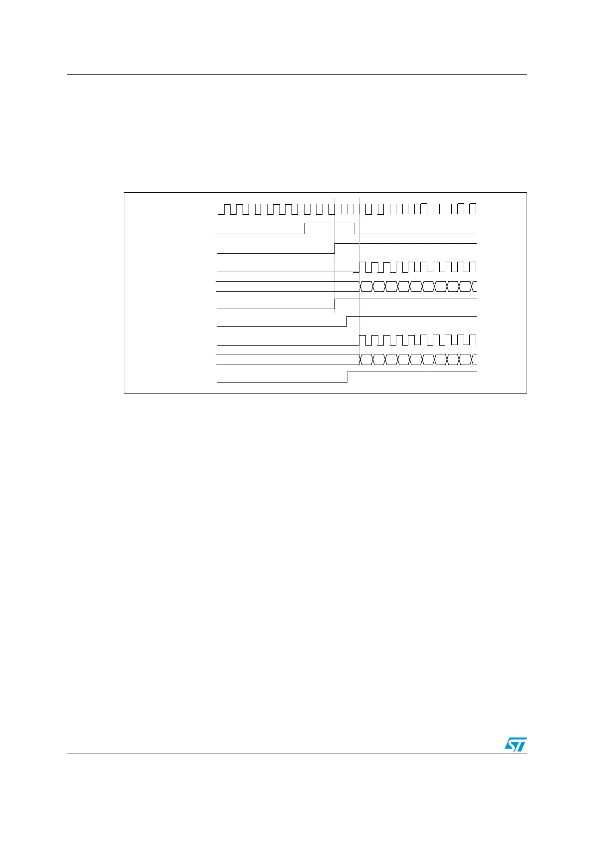
When a rising edge occurs on TI1 (Timer 1), both counters starts counting synchronously on
the internal clock and both TIF flags are set.
Note: In this example both timers are initialized before starting (by setting their respective UG
bits). Both counters starts from 0, but you can easily insert an offset between them by
writing any of the counter registers (TIMx_CNT). You can see that the master/slave mode
insert a delay between CNT_EN and CK_PSC on timer 1.
Figure 136. Triggering timer 1 and 2 with timer 1 TI1 input
16.3.16 Debug mode
When the microcontroller enters debug mode (Cortex™-M0 core - halted), the TIMx counter
either continues to work normally or stops, depending on DBG_TIMx_STOP configuration
bit in DBGMCU module.
00 01
CK_INT
TIMER1-CEN=CNT_EN
TIMER1-CNT
TIMER 1-TI1
TIMER 1-CK_PSC
02 03 04 05 06 07 08 09
TIMER1-TIF
00 01
TIMER2-CEN=CNT_EN
TIMER2-CNT
TIMER 2-CK_PSC
02 03 04 05 06 07 08 09
TIMER2-TIF