RM0091 Analog-to-digital converter (ADC)
Doc ID 018940 Rev 1 187/742
Note: Please refer to the Section 7: Reset and clock control (RCC) on page 82 for the description
of how to manage the dedicated 14 MHz internal oscillator. The ADC interface can
automatically switch ON/OFF the 14 MHz internal oscillator to save power.
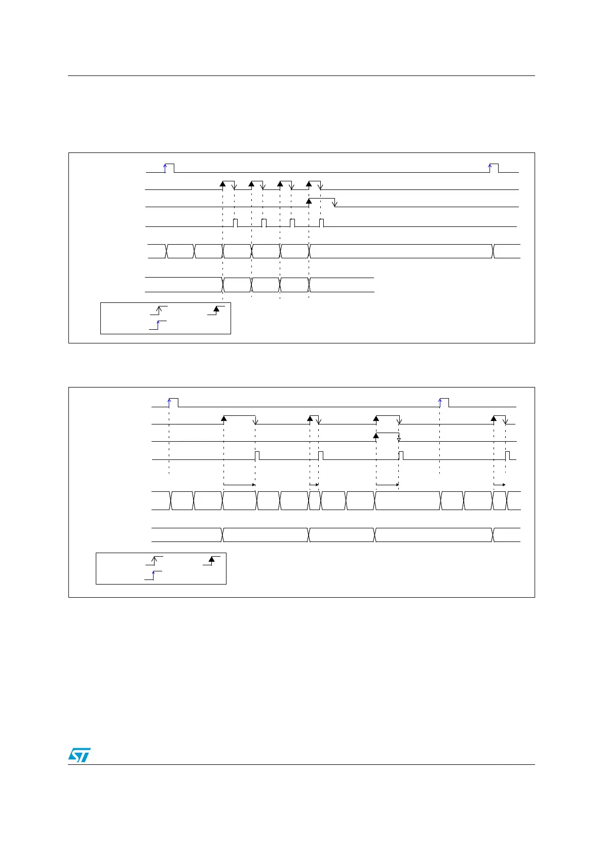
Figure 34. Behavior withWAIT=0, AUTOFF=1
1. EXTSEL=TRGx, EXTEN=0x1 (rising edge), CONT=x, ADSTART=1, CHSEL=0xF, SCANDIR=0, WAIT=1,
AUTOFF=1
Figure 35. Behavior with WAIT=1, AUTOFF=1
1. EXTSEL=TRGx, EXTEN=0x1 (rising edge), CONT=x, ADSTART=1, CHSEL=0xF, SCANDIR=0, WAIT=1,
AUTOFF=1
12.8 Analog window watchdog (AWDEN, AWDSGL, AWDCH,
AWD_HTR/LTR, AWD)
The AWD analog watchdog feature is enabled by setting the AWDEN bit in the
ADC_CFGR1 register. It is used to monitor that either one selected channel or all enabled
channels
(see Table 36: Analog watchdog channel selection)
remain within a configured
voltage range (window) as shown in Figure 36.
TRGx
EOC
EOSEQ
ADC_DR Read access
ADC state
ADC_DR
RDY Startup CH1 CH2 CH3 CH4
D1 D4
OFF
Startup
by S/W by H/W
triggered
D2 D3
DLY
TRGx
EOC
EOSEQ
ADC_DR Read access
ADC state
ADC_DR
RDY Start CH1 OFF
D1
CH2
OFF
CH3 OFF
D2 D3
CH1
D4
DLYDLY DLY
CH2
by S/W by H/W
triggered
up
Start
up
Start
up
Start
up
OFF