Debug support (DBG) RM0091
722/742 Doc ID 018940 Rev 1
29.5.2 SW protocol sequence
Each sequence consist of three phases:
1. Packet request (8 bits) transmitted by the host
2. Acknowledge response (3 bits) transmitted by the target
3. Data transfer phase (33 bits) transmitted by the host or the target
Refer to the Cortex-M0 TRM for a detailed description of DPACC and APACC registers.
The packet request is always followed by the turnaround time (default 1 bit) where neither
the host nor target drive the line.
The ACK Response must be followed by a turnaround time only if it is a READ transaction or
if a WAIT or FAULT acknowledge has been received.
The DATA transfer must be followed by a turnaround time only if it is a READ transaction.
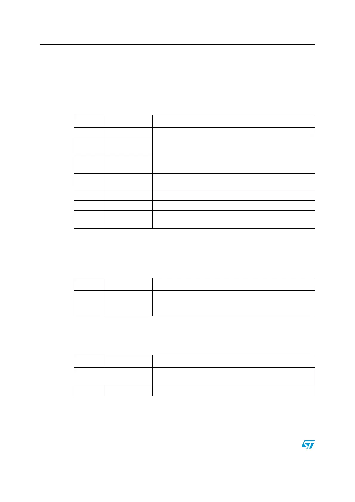
Table 108. Packet request (8-bits)
Bit Name Description
0 Start Must be “1”
1 APnDP
0: DP Access
1: AP Access
2RnW
0: Write Request
1: Read Request
4:3 A(3:2)
Address field of the DP or AP registers (refer to Table 112 on
page 725)
5 Parity Single bit parity of preceding bits
6Stop 0
7Park
Not driven by the host. Must be read as “1” by the target
because of the pull-up
Table 109. ACK response (3 bits)
Bit Name Description
0..2
ACK
001: FAULT
010: WAIT
100: OK
Table 110. DATA transfer (33 bits)
Bit Name Description
0..31
WDATA or
RDATA
Write or Read data
32
Parity
Single parity of the 32 data bits