RM0091 Inter-integrated circuit (I
2
C) interface
Doc ID 018940 Rev 1 475/742
SDADEL <= {t
HD;DAT (max)
-260 ns - [(DNF+3) x t
I2CCLK
]} / {(PRESC +1) x t
I2CCLK
}
Note: -50 ns / -260 ns are part of the equation only when the analog filter is enabled.
Refer to Table 64.: I2C-SMBUS specification data setup and hold times for t
f
and
t
HD;DAT
standard values.
● After sending SDA output, SCL line is kept at low level during the setup time. This setup
time is
t
SCLDEL
= (SCLDEL+1) x t
PRESC
where t
PRESC
= (PRESC+1) x t
I2CCLK.
t
SCLDEL
impacts the setup time t
SU;DAT .
In order to bridge the undefined region of the SDA transition (rising edge usually worst
case), you must program SCLDEL in such a way that:
{[t
r (max)
+ t
SU;DAT (min)
] / [ (PRESC+1)] x t
I2CCLK
]} - 1 <= SCLDEL
Refer to Table 64.: I2C-SMBUS specification data setup and hold times for t
r
and
t
SU;DAT
standard values.
Additionally, in master mode, the SCL clock high and low levels must be configured by
programming the PRESC[3:0], SCLH[7:0] and SCLL[7:0] bits in the I2Cx_TIMINGR register.
● When the SCL falling edge is internally detected, a delay is inserted before releasing
the SCL output. This delay is
t
SCLL
= (SCLL+1) x t
PRESC
where t
PRESC
= (PRESC+1) x
t
I2CCLK.
t
SCLL
impacts the SCL low time t
LOW .
● When the SCL rising edge is internally detected, a delay is inserted before forcing the
SCL output to low level. This delay is
t
SCLH
= (SCLH+1) x t
PRESC
where t
PRESC
=
(PRESC+1) x t
I2CCLK.
t
SCLH
impacts the SCL high time t
HIGH .
Refer to section : I2C master initialization for more details.
Caution: Changing the timing configuration is not allowed when the I2C is enabled.
I2C configuration
The I2C slave NOSTRETCH mode must also be configured before enabling the peripheral.
Refer to : I2C slave initialization for more details.
Caution: Changing the NOSTRETCH configuration is not allowed when the I2C is enabled.
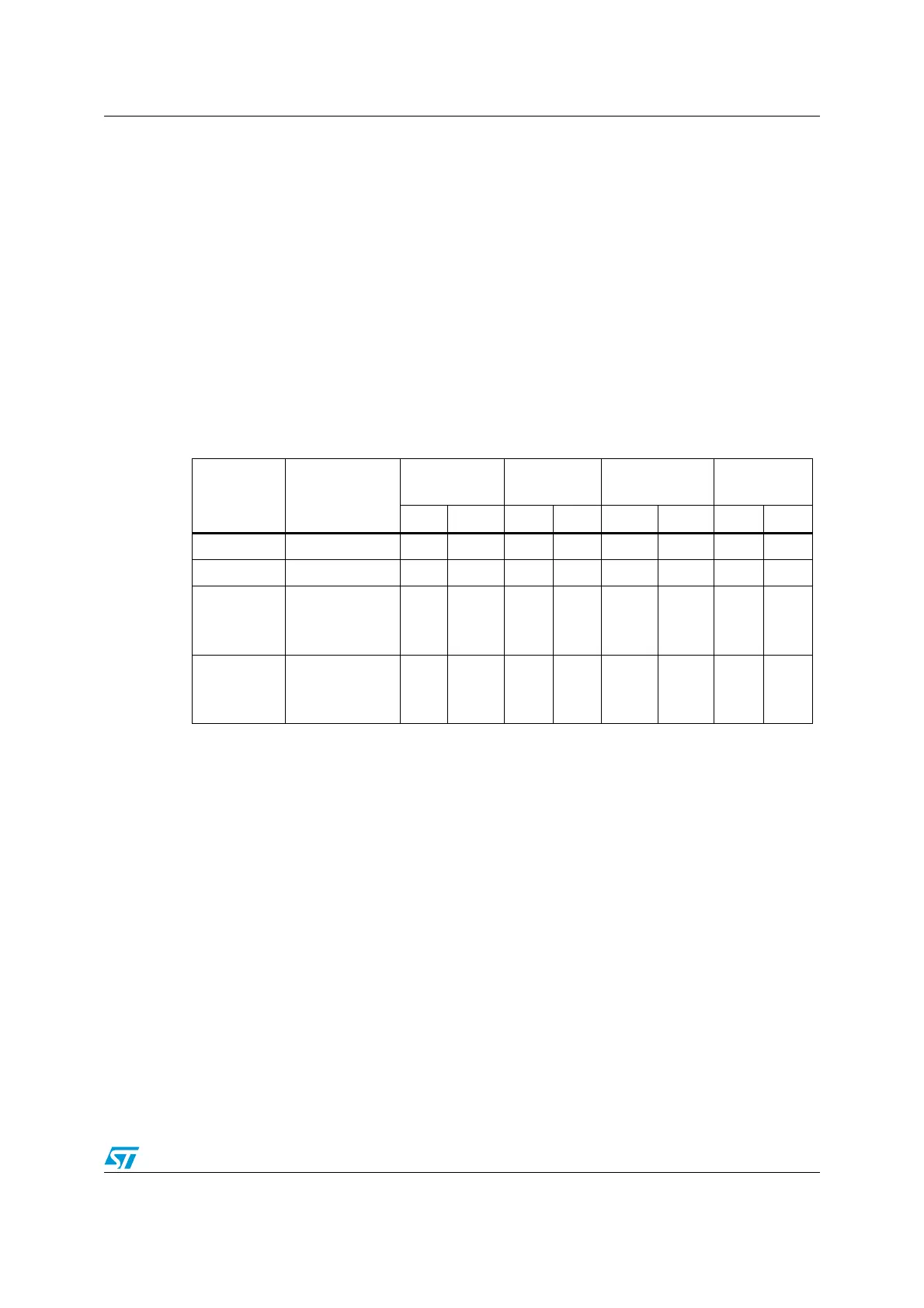
Table 64. I2C-SMBUS specification data setup and hold times
Parameter Standard Fast Mode Fast Mode
Plus
SMBUS
Min. Max Min. Max Min. Max Min. Max
t
HD;DAT
(us) Data hold time 0 3.45 0 0.9 0 0.45 300
t
SU;DAT
(ns) Data setup time 250 100 50 250
tr(ns)
rise time of
both SDA and
SCL signals
1000 300 120 1000
t
f
(ns)
fall time of
both SDA and
SCL signals
300 300 120 300