Analog-to-digital converter (ADC) RM0091
186/742 Doc ID 018940 Rev 1
When the WAIT bit is set to 1 in the ADC_CFGR1 register, a new conversion can start only
if the previous data has been treated, once the ADC_DR register has been read or if the
EOC bit has been cleared.
This is a way to automatically adapt the speed of the ADC to the speed of the system that
reads the data.
Note: Any hardware triggers which occur while a conversion is ongoing or during the wait time
preceding the read access are ignored.
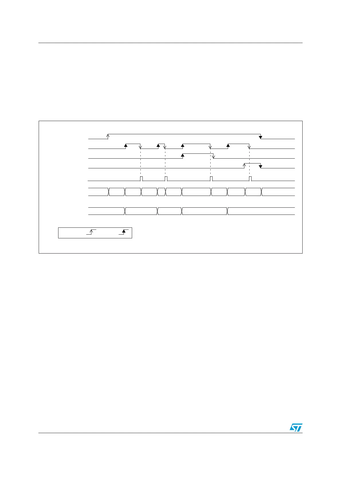
Figure 33. Wait mode conversion (continuous mode, software trigger)
1. EXTEN=0x0, CONT=1
2. CHSEL=0x3, SCANDIR=0, WAIT=1, AUTOFF=0
12.7.2 Auto-off mode (AUTOFF)
The ADC has an automatic power management feature which is called auto-off mode, and
is enabled by setting AUTOFF=1 in the ADC_CFGR1 register.
When AUTOFF=1, the ADC is always powered off when not converting and automatically
wakes-up when a conversion is started (by software or hardware trigger). A startup-time is
automatically inserted between the trigger event which starts the conversion and the
sampling time of the ADC. The ADC is then automatically disabled once the sequence of
conversions is complete.
Auto-off mode can cause a dramatic reduction in the power consumption of applications
which need relatively few conversions or when conversion requests are timed far enough
apart (for example with a low frequency hardware trigger) to justify the extra power and extra
time used for switching the ADC on and off.
Auto-off mode can be combined with the wait mode conversion (WAIT=1) for applications
clocked at low frequency. This combination can provide significant power savings if the ADC
is automatically powered-off during the wait phase and restarted as soon as the ADC_DR
register is read by the application (see Figure 35: Behavior with WAIT=1, AUTOFF=1).
ADSTART
EOC
EOSEQ
ADSTP
ADC_DR Read access
ADC state
ADC_DR
RDY CH1 DLY CH2 DLY CH3 DLY
CH1 DLY STOP RDY
D1 D2 D3 D1
by S/W by H/W