RM0091 Universal synchronous asynchronous receiver transmitter (USART)
Doc ID 018940 Rev 1 577/742
25.5.2 Transmitter
The transmitter can send data words of either 8 or 9 bits depending on the M bit status. The
Transmit Enable bit (TE) must be set in order to activate the transmitter function. The data in
the transmit shift register is output on the TX pin and the corresponding clock pulses are
output on the SCLK pin.
Character transmission
During an USART transmission, data shifts out least significant bit first (default
configuration) on the TX pin. In this mode, the USART_TDR register consists of a buffer
(TDR) between the internal bus and the transmit shift register (see Figure 228).
Every character is preceded by a start bit which is a logic level low for one bit period. The
character is terminated by a configurable number of stop bits.
The following stop bits are supported by USART: 1, 1.5 and 2 stop bits.
Note: The TE bit must be set before writing the data to be transmitted to the USART_TDR.
An idle frame will be sent after the TE bit is enabled.
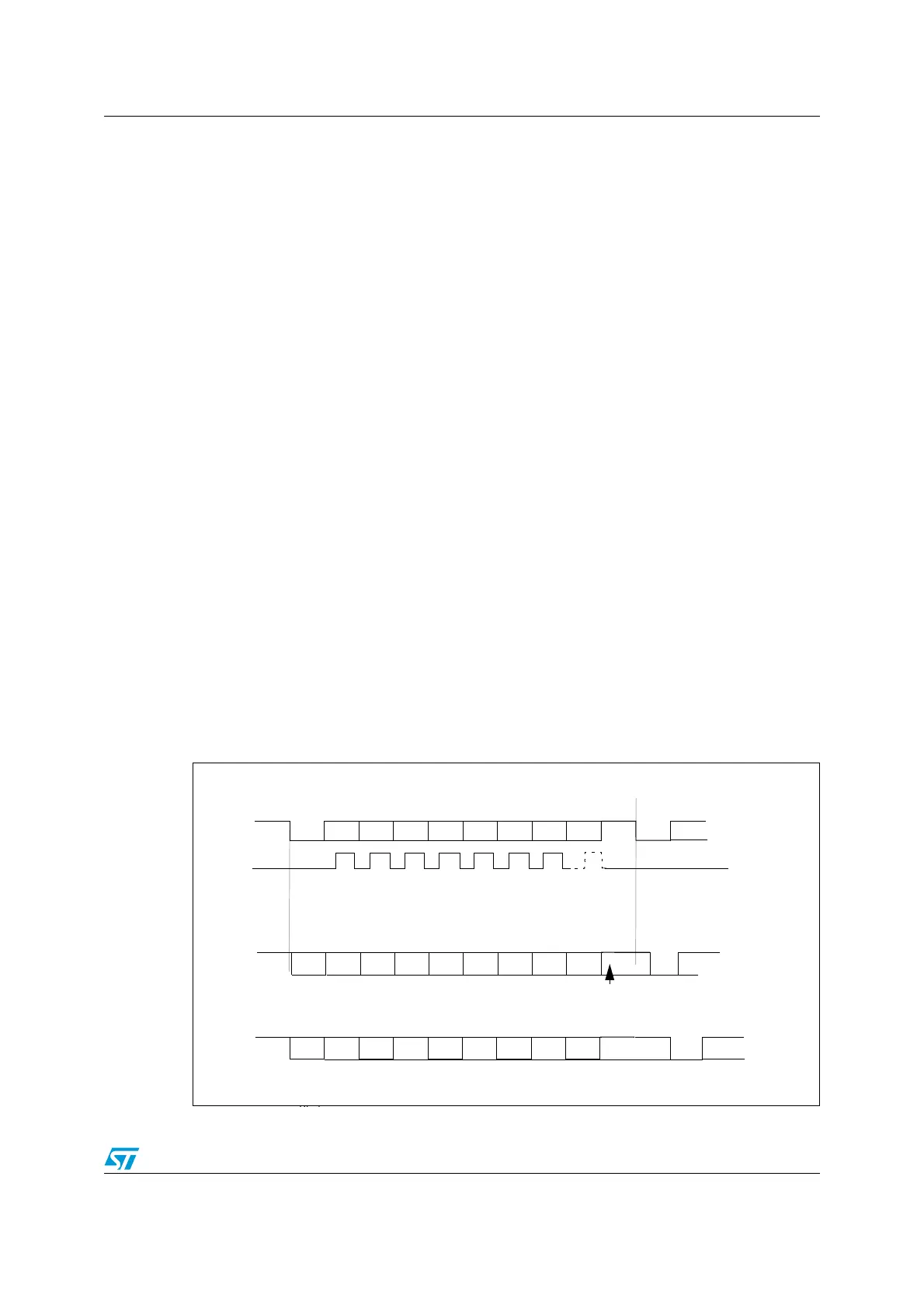
Configurable stop bits
The number of stop bits to be transmitted with every character can be programmed in
Control register 2, bits 13,12.
1. 1 stop bit: This is the default value of number of stop bits.
2. 2 Stop bits: This will be supported by normal USART, single-wire and modem modes.
3. 1.5 stop bits: To be used in Smartcard mode.
An idle frame transmission will include the stop bits.
A break transmission will be 10 low bits (when m = 0) or 11 low bits (when m = 1) followed
by 2 stop bits. It is not possible to transmit long breaks (break of length greater than 10/11
low bits).
Figure 230. Configurable stop bits
Bit0
Bit1
Bit2
Bit3
Bit4
Bit5
Bit6
Bit7
Start
Bit
Stop
bit
Next
start
bit
8-bit Word length (M bit is reset)
Possible
parity
bit
Data frame
Next data frame
****
** LBCL bit controls last data clock pulse
CLOCK
**
Bit0
Bit1
Bit2
Bit3
Bit4
Bit5
Bit6
Bit7
Start
Bit
2 Stop
Bits
Next
Start
Bit
Possible
parity
bit
Data frame
Next data frame
St t
Next data frame
Bit0
Bit1
Bit2
Bit3
Bit4
Bit5
Bit6
Bit7
Start
Bit
Next
start
bit
Possible
Parity
Bit
Data frame
Next data frame
1 1/2 stop bits
a) 1 Stop Bit
b) 1 1/2 stop Bits
c) 2 Stop Bits

 Loading...