Analog-to-digital converter (ADC) RM0091
196/742 Doc ID 018940 Rev 1
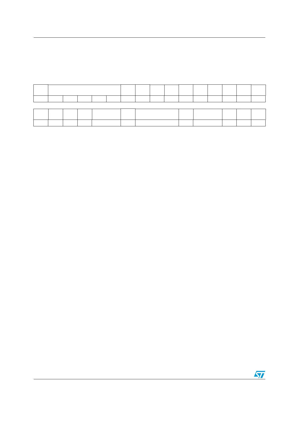
12.12.4 ADC configuration register 1 (ADC_CFGR1)
Address offset: 0x0C
Reset value: 0x0000 0000
31 30 29 28 27 26 25 24 23 22 21 20 19 18 17 16
Res. AWDCH[4:0] Res. Res.
AWD
EN
AWD
SGL
Res. Res. Res. Res. Res.
DISC
EN
rw rw rw rw rw rw rw rw
1514131211109876543210
AUT
OFF
AUT
DLY
CONT
OVR
MOD
EXTEN[1:0] Res. EXTSEL[2:0] ALIGN RES[1:0]
SCAN
DIR
DMA
CFG
DMA
EN
rw rw rw rw rw rw rw rw rw rw rw
Bit 31 Reserved, must be kept at reset value.
Bits 30:26 AWDCH[4:0]: Analog watchdog channel selection
These bits are set and cleared by software. They select the input channel to be guarded by the analog
watchdog.
00000: ADC analog input Channel 0 monitored by AWD
00001: ADC analog input Channel 1 monitored by AWD
.....
10011: ADC analog input Channel 18 monitored by AWD
other values: Reserved, must not be used
Note: The channel selected by the AWDCH[4:0] bits must be also set into the CHSELR register
Note: Software is allowed to write these bits only when ADSTART=0 (which ensures that no
conversion is ongoing).
Bits 29:24 Reserved, must be kept at reset value.
Bit 23 AWDEN: Analog watchdog enable
This bit is set and cleared by software.
0: Analog watchdog disabled
1: Analog watchdog enabled
Note: Software is allowed to write this bit only when ADSTART=0 (which ensures that no conversion
is ongoing).
Bit 22 AWDSGL: Enable the watchdog on a single channel or on all channels
This bit is set and cleared by software to enable the analog watchdog on the channel identified by the
AWDCH[4:0] bits or on all the channels
0: Analog watchdog enabled on all channels
1: Analog watchdog enabled on a single channel
Note: Software is allowed to write this bit only when ADSTART=0 (which ensures that no conversion
is ongoing).
Bits 21:17 Reserved, must be kept at reset value.