RM0091 System and memory overview
Doc ID 018940 Rev 1 35/742
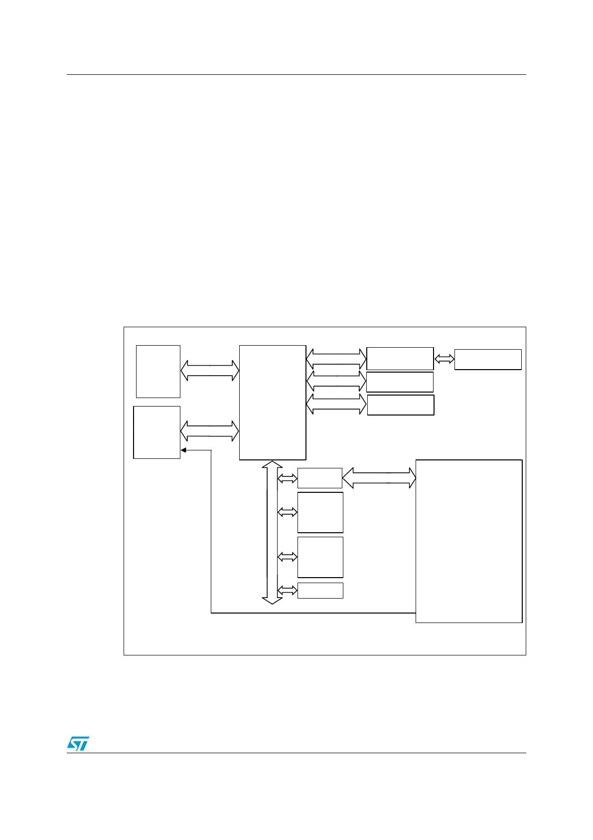
2 System and memory overview
2.1 System architecture
The main system consists of:
● Two masters:
– Cortex-M0 core AHB bus
– GP-DMA (general-purpose DMA)
● Four slaves:
– Internal SRAM
– Internal Flash memory
– AHB to APB, which connects all the APB peripherals
– AHB dedicated to GPIO ports
These are interconnected using a multilayer AHB bus architecture as shown in Figure 1:
Figure 1. System architecture
System bus
This bus connects the system bus of the Cortex-M0 core (peripherals bus) to a BusMatrix
which manages the arbitration between the core and the DMA.
MS19217V1
Busmatrix
AHB2 bus
APB bus
FLITF
Flash interface
SRAM
AHB2APB
Bridge
Cortex
M0
DMA
Controller
(Channels
1 to 5)
System bus
DMA
SYSCFG
ADC
DAC
COMP
TIM1
TIM2,TIM3
TIM14,TIM15,TIM16,TIM17
TIM6
IWWDG
WWDG
RTC
I2C1, I2C2
USART1, USART2
SPI1/I2S1, SPI2
HDMI-CEC
DBGMCU
AHB1 bus
Reset and
clock
controller
(RCC)
Touch
sensing
controller
(TSC)
CRC
DMA request
GPIO Ports
A,B,C,D,F
Flash memory