RM0091 Independent watchdog (IWDG)
Doc ID 018940 Rev 1 455/742
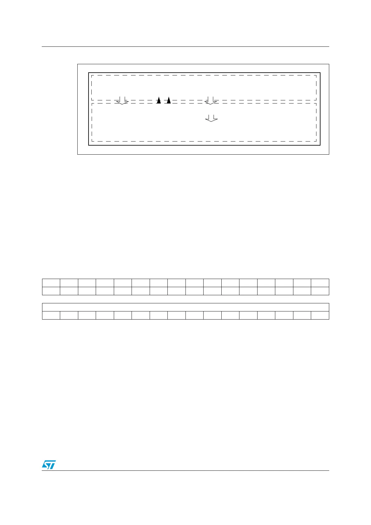
Figure 192. Independent watchdog block diagram
Note: The watchdog function is implemented in the CORE voltage domain that is still functional in
Stop and Standby modes.
21.4 IWDG registers
Refer to Section 1.1 on page 34 for a list of abbreviations used in register descriptions.
The peripheral registers can be accessed by half-words (16-bit) or words (32-bit).
21.4.1 Key register (IWDG_KR)
Address offset: 0x00
Reset value: 0x0000 0000 (reset by Standby mode)
IWDG reset
prescaler
12-bit downcounter
IWDG_PR
Prescaler register
IWDG_RLR
Reload register
8-bit
LSI
IWDG_KR
Key register
CORE
V
DD
voltage domain
IWDG_SR
Status register
12-bit reload value
MS19944V1
31 30 29 28 27 26 25 24 23 22 21 20 19 18 17 16
Res. Res. Res. Res. Res. Res. Res. Res. Res. Res. Res. Res. Res. Res. Res. Res.
1514131211109876543210
KEY[15:0]
wwwwwwwwwwwwwwww
Bits 31:16 Reserved, must be kept at reset value.
Bits 15:0 KEY[15:0]: Key value (write only, read 0x0000)
These bits must be written by software at regular intervals with the key value 0xAAAA,
otherwise the watchdog generates a reset when the counter reaches 0.
Writing the key value 0x5555 to enables access to the IWDG_PR, IWDG_RLR and
IWDG_WINR registers (see Section 21.3.3)
Writing the key value CCCCh starts the watchdog (except if the hardware watchdog option is
selected)