RM0091 Inter-integrated circuit (I
2
C) interface
Doc ID 018940 Rev 1 471/742
23.4.2 I2C2 block diagram
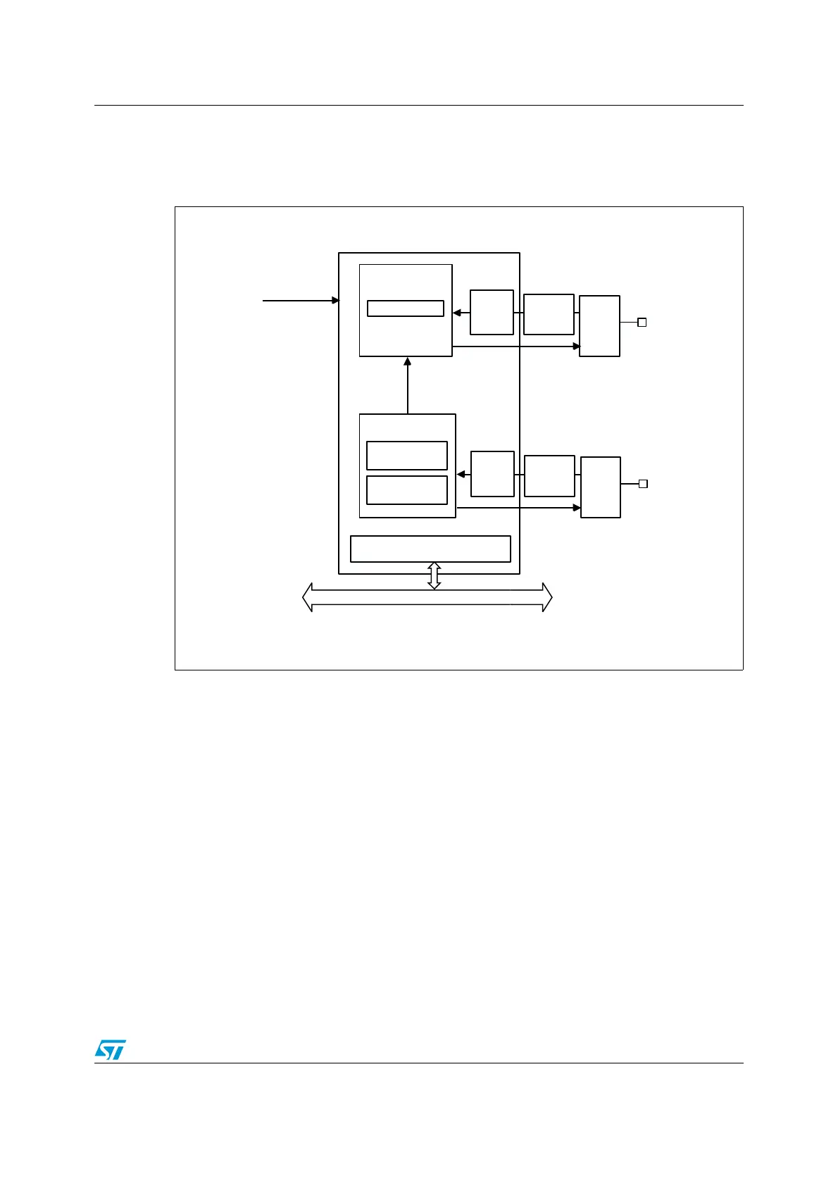
The block diagram of the I
2
C2 interface is shown in Figure 195.
Figure 196. I
2
C2 block diagram
23.4.3 I
2
C clock requirements
The I2C kernel is clocked by I2CCLK.
The I2CCLK period t
I2CCLK
must respect the following conditions:
t
I2CCLK
< (t
LOW
- t
filters
) / 4 and t
I2CCLK
< t
HIGH
with:
t
LOW
: SCL low time and t
HIGH
: SCL high time
t
filters
: when enabled, sum of the delays brought by the analog filter and by the digital filter.
Analog filter delay is maximum 260 ns. Digital filter delay is DNF
x t
I2CCLK
.
The PCLK clock period t
PCLK
must respect the following condition:
t
PCLK
< 4/3 t
SCL
with t
SCL
: SCL period
Caution: When the I2C kernel is clocked by PLCK, PCLK must respect the conditions for t
I2CCLK
.
MS19874V1
Shift register
Data control
Clock control
Master clock
generation
Slave clock
stretching
Digital
noise
filter
I2C2_SCL
PCLK
Registers
APB bus
GPIO
logic
Analog
noise
filter
Digital
noise
filter
I2C2_SDA
GPIO
logic
Analog
noise
filter