Reset and clock control (RCC) RM0091
82/742 Doc ID 018940 Rev 1
7 Reset and clock control (RCC)
7.1 Reset
There are three types of reset, defined as system reset, power reset and backup domain
reset.
7.1.1 System reset
A system reset sets all registers to their reset values except the reset flags in the clock
controller CSR register and the registers in the Backup domain (see Figure 6 on page 74).
A system reset is generated when one of the following events occurs:
1. A low level on the NRST pin (external reset)
2. Window watchdog event (WWDG reset)
3. Independent watchdog event (IWWDG reset)
4. A software reset (SW reset) (see Software reset)
5. Low-power management reset (see Low-power management reset)
6. Option byte loader reset (see Option byte loader reset)
The reset source can be identified by checking the reset flags in the Control/Status register,
RCC_CSR (see Section 7.4.10: Control/status register (RCC_CSR)).
These sources act on the NRST pin and it is always kept low during the delay phase. The
RESET service routine vector is fixed at address 0x0000_0004 in the memory map.
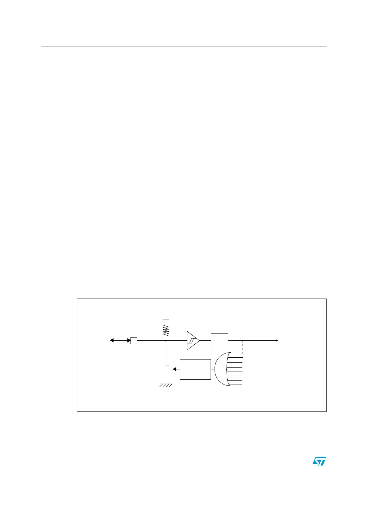
The system reset signal provided to the device is output on the NRST pin. The pulse
generator guarantees a minimum reset pulse duration of 20 µs for each reset source
(external or internal reset). In case of an external reset, the reset pulse is generated while
the NRST pin is asserted low.
Figure 9. Simplified diagram of the reset circuit
NRST
R
PU
V
DD
WWDG reset
IWWDG reset
Pulse
generator
Power reset
External
reset
(min 20 μs)
System reset
Filter
Software reset
Low-power management reset
Option byte loader reset
Exit from Standby mode
MS19841V1