RM0091 Analog-to-digital converter (ADC)
Doc ID 018940 Rev 1 177/742
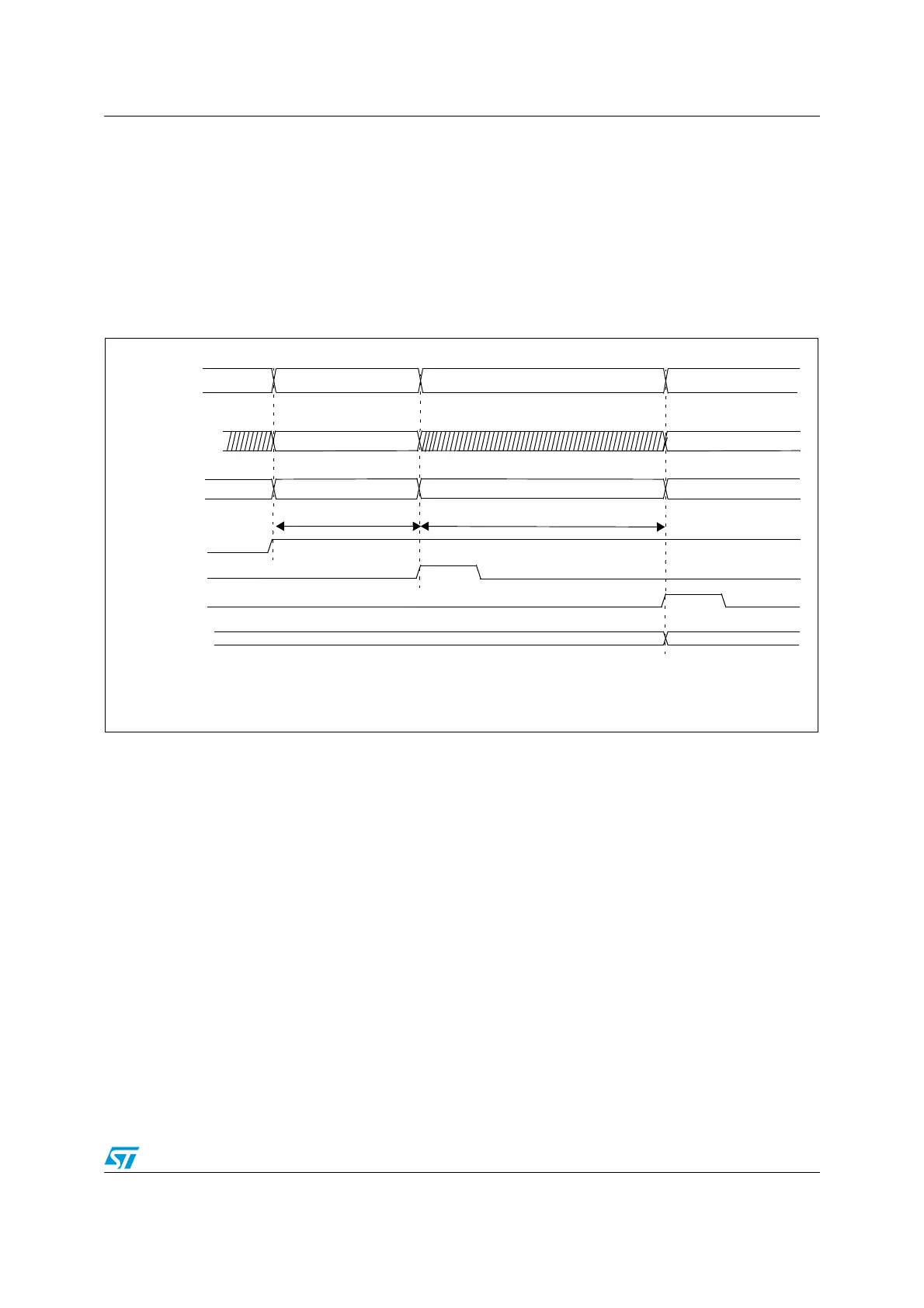
12.4.10 Timings
The elapsed time between the start of a conversion and the end of conversion is the sum of
the configured sampling time plus the successive approximation time depending on data
resolution:
Figure 25. Analog to digital conversion time
12.4.11 Stopping an ongoing conversion (ADSTP)
The software can decide to stop any ongoing conversions by setting ADSTP=1 in the
ADC_CR register.
This will reset the ADC operation and the ADC will be idle, ready for a new operation.
When the ADSTP bit is set by software, any ongoing conversion is aborted and the result is
discarded (ADC_DR register is not updated with the current conversion).
The scan sequence is also aborted and reset (meaning that restarting the ADC would re-
start a new sequence)
Once this procedure is complete, the ADSTP and ADSTART bits are both cleared by
hardware and the software must wait until ADSTART=0 before starting new conversions.
t
ADC
= t
SMPL
+ t
SAR
= [ 1.5
|min
+ 12.5
|12bit
] x t
ADC_CLK
t
ADC
= t
SMPL
+ t
SAR
= 107.1 ns
|min
+ 892.8 ns
|12bit
= 1 µs
|min
(for f
ADC_CLK
= 14 MHz)
Analog channel
SAMPLING CH(N)
CH(N) CH(N+1)
Sample AIN(N) Hold AIN(N)
ADC state
RDY
CONVERTING CH(N)
ADC_DR
DATA N-1 DATA N
Sample AIN(N+1)
Internal S/H
t
SMPL
(1)
t
SAR
(2)
SAMPLING CH(N+1)
(1) t
SMPL
depends on SMP[2:0]
(2) t
SAR
depends on RES[2:0]
EOC
ADSTART
cleared
by SW
set
by HW
set
by SW
EOSMP
cleared
by SW
set
by HW