RM0091 Universal synchronous asynchronous receiver transmitter (USART)
Doc ID 018940 Rev 1 597/742
Apart from this, the communication protocol is similar to normal USART mode. Any conflicts
on the line must be managed by software (by the use of a centralized arbiter, for instance).
In particular, the transmission is never blocked by hardware and continues as soon as data
is written in the data register while the TE bit is set.
25.5.13 Smartcard mode
This section is relevant only when Smartcard mode is supported. Please refer to
Section 25.4: USART implementation on page 573.
Smartcard mode is selected by setting the SCEN bit in the USART_CR3 register. In
Smartcard mode, the following bits must be kept cleared:
● LINEN bit in the USART_CR2 register,
● HDSEL and IREN bits in the USART_CR3 register.
Moreover, the CLKEN bit may be set in order to provide a clock to the Smartcard.
The Smartcard interface is designed to support asynchronous protocol Smartcards as
defined in the ISO 7816-3 standard. Both T=0 (character mode) and T=1 (block mode) are
supported.
The USART should be configured as:
● 8 bits plus parity: where M=1 and PCE=1 in the USART_CR1 register
● 1.5 stop bits: where STOP=11 in the USART_CR2 register.
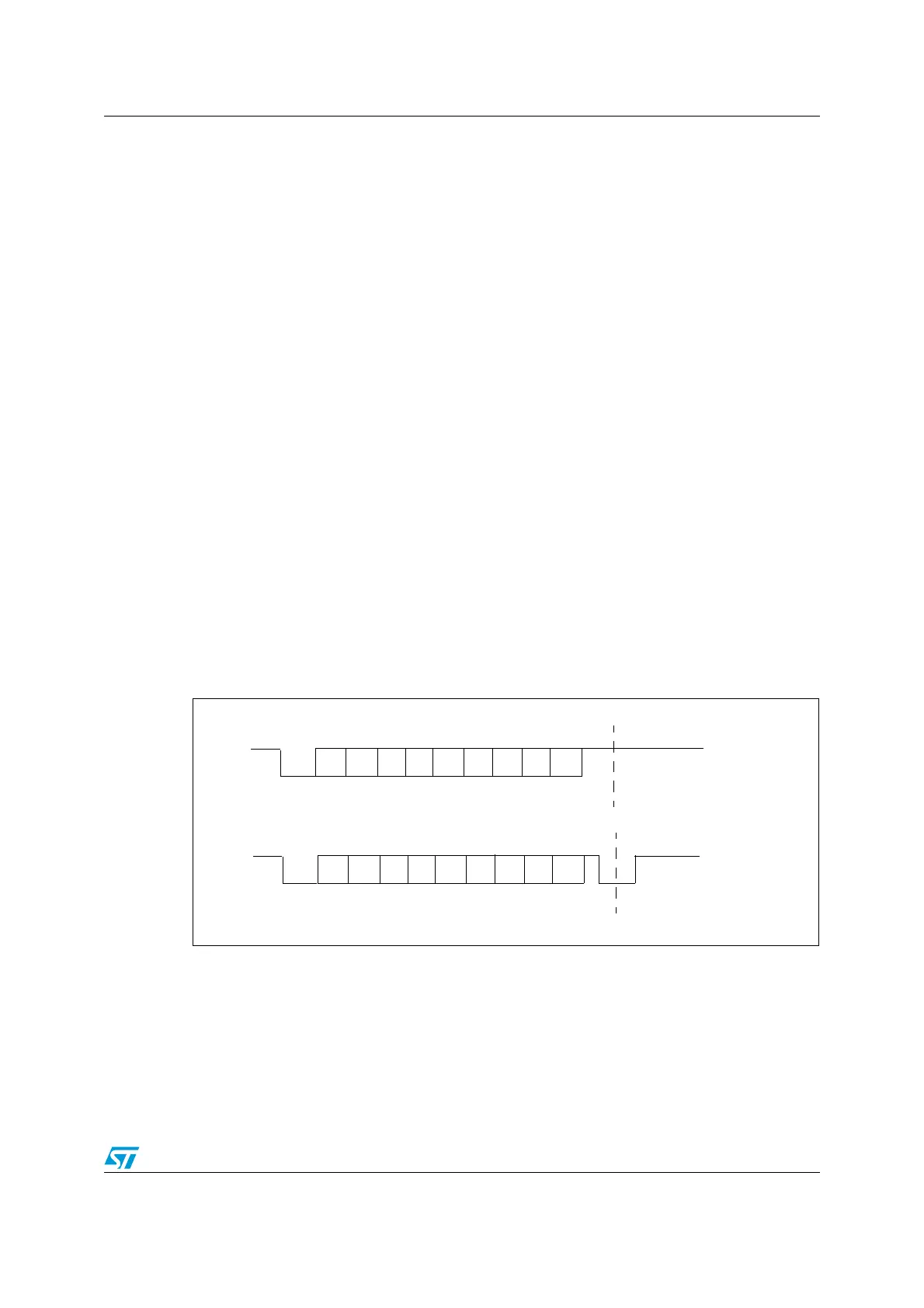
In T=0 (character) mode, the parity error is indicated at the end of each character during the
guard time period.
Figure 243 shows examples of what can be seen on the data line with and without parity
error.
Figure 243. ISO 7816-3 asynchronous protocol
When connected to a Smartcard, the TX output of the USART drives a bidirectional line that
is also driven by the Smartcard. The TX pin must be configured as open drain.
Smartcard mode implements a single wire half duplex communication protocol.
● Transmission of data from the transmit shift register is guaranteed to be delayed by a
minimum of 1/2 baud clock. In normal operation a full transmit shift register starts
S
0
1
23
5
4
67
P
Start
bit
Guard time
S
0
1
23
5
4
67
P
Start
bit
Line pulled low
by receiver during stop in
case of parity error
Guard time
Without Parity error
With Parity error