RM0091 Analog-to-digital converter (ADC)
Doc ID 018940 Rev 1 199/742
12.12.5 ADC configuration register 2 (ADC_CFGR2)
Address offset: 0x10
Reset value: 0x0000 1000
Bit 0 DMAEN: Direct memory access enable
This bit is set and cleared by software to enable the generation of DMA requests. This allows to use
the DMA controller to manage automatically the converted data. For more details, refer to
Section 12.6.5: Managing converted data using the DMA on page 184.
0: DMA disabled
1: DMA enabled
Note: Software is allowed to write this bit only when ADSTART=0 (which ensures that no conversion
is ongoing).
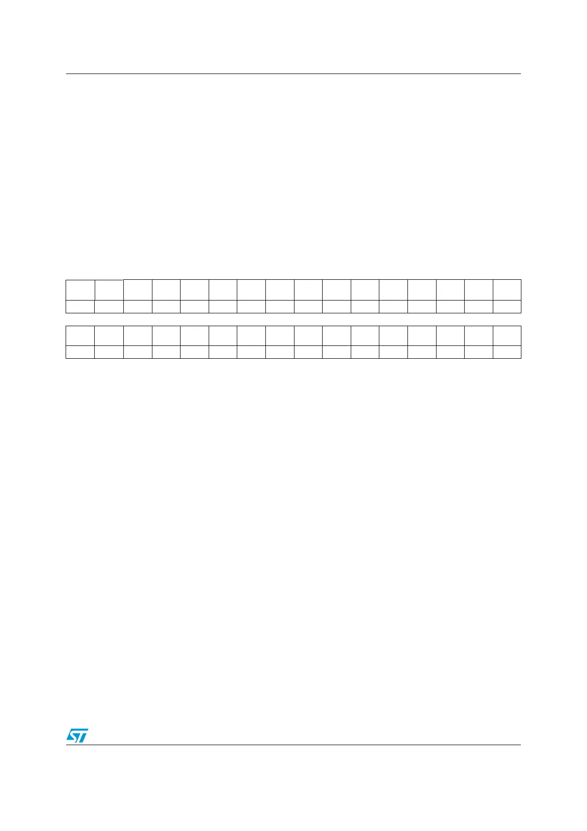
31 30 29 28 27 26 25 24 23 22 21 20 19 18 17 16
JITOFF
_D4
JITOFF
_D2
Res. Res. Res. Res. Res. Res. Res. Res. Res. Res. Res. Res. Res. Res.
rw rw
1514131211109876543210
Res. Res. Res. Res. Res. Res. Res. Res. Res. Res. Res. Res. Res. Res. Res. Res.
Bits 31 JITOFF_D4: Remove jitter in “trigger-to-start of conversion” delay when ADC clock is driven by PLCK
divided by 4
This bit is set and cleared by software. It must be configured by software only when driving the ADC
clock with PLCK divided by 4.
When driving the ADC clock with the dedicated 14 MHz oscillator, this bit must be kept cleared.
When set, it enables a mechanism which removes the jitter on the duration between the trigger and the
start of conversion.
0: Jitter not removed
1: Jitter removed if ADC clock is driven by PCLK divided by 4
Note: Software is allowed to write these bits only when ADSTART=0 (which ensures that no
conversion is ongoing).
Note: When JITOFF_DIV4 is set, bit JITOFF_DIV2 must be kept cleared
Bits 30 JITOFF_D2: Remove Jitter in “trigger-to-start of conversion” delay when ADC clock is driven by PLCK
divided by 2
This bit is set and cleared by software. It must be configured by software only when driving the ADC
clock with PLCK divided by 2.
When feeding the ADC clock with the dedicated 14 MHz oscillator, this bit must be kept cleared.
When set, it enables a mechanism which removes the jitter on the duration between the trigger and the
start of conversion.
0: Jitter not removed
1: Jitter removed if ADC clock is driven by PCLK divided by 2
Note: Software is allowed to write these bits only when ADSTART=0 (which ensures that no
conversion is ongoing).
Note: When JITOFF_DIV2 is set, bit JITOFF_DIV4 must be kept cleared
Bits 29:0 Reserved, must be kept at reset value.