Interrupts and events RM0091
162/742 Doc ID 018940 Rev 1
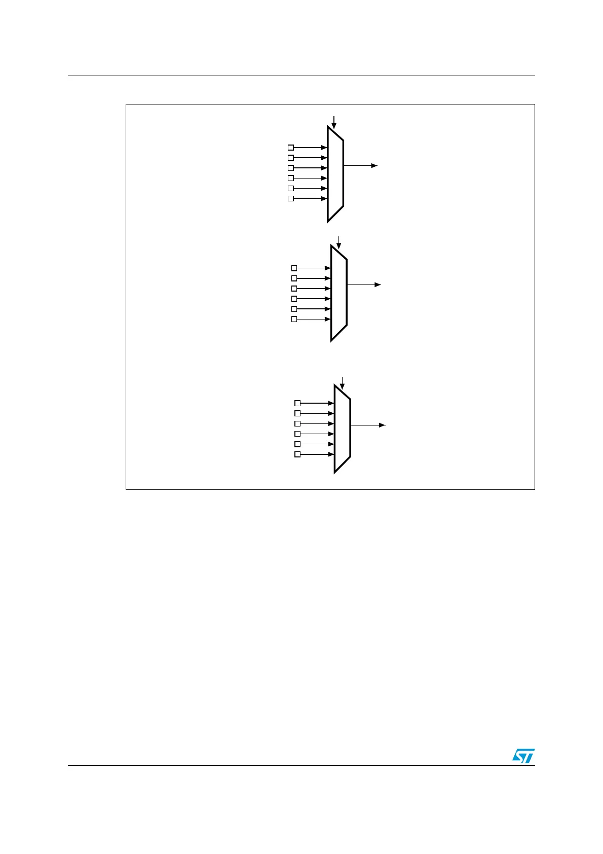
Figure 21. External interrupt/event GPIO mapping
The remaining lines are connected as follow:
● EXTI line 16 is connected to the PVD output
● EXTI line 17 is connected to the RTC Alarm event
● EXTI line 18 is reserved (internally held low)
● EXTI line 19 is connected to RTC tamper and Timestamps
● EXTI line 20 is reserved (internally held low)
● EXTI line 21 is connected to Comparator 1 output
● EXTI line 22 is connected to Comparator 2 output
● EXTI line 23 is connected to I2C1 wakeup
● EXTI line 24 is reserved (internally held low)
● EXTI line 25 is connected to USART1 wakeup
● EXTI line 26 is reserved (internally held low)
● EXTI line 27 is connected to CEC wakeup.
Note: EXTI lines 18, 20, 23, 24, 25, 26 and 27 are internal.
PA0
PB0
PC0
PD0
PE0
PF0
PA1
PB1
PC1
PD1
PE1
PF1
PA15
PB15
PC15
PD15
PE15
PF15
EXTI0
EXTI1
EXTI15
EXTI15[3:0] bits in the SYSCFG_EXTICR4 register
. . .
EXTI1[3:0] bits in the SYSCFG_EXTICR1 register
EXTI0[3:0] bits in the SYSCFG_EXTICR1 register
MS19951V1