8-118 Xerox Internal Use Only Phaser 6500/WorkCentre 6505 Service Manual
Service Parts Disassembly
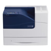
7. Release the harnesses from the locking clamp and pull the harness out from
the hole in the chassis.
8. Remove three screws (one silver, M4, 6mm; one silver, M3, 6mm; one silver,
tap, 8mm) that attach the Feed Drive Assembly to the printer.
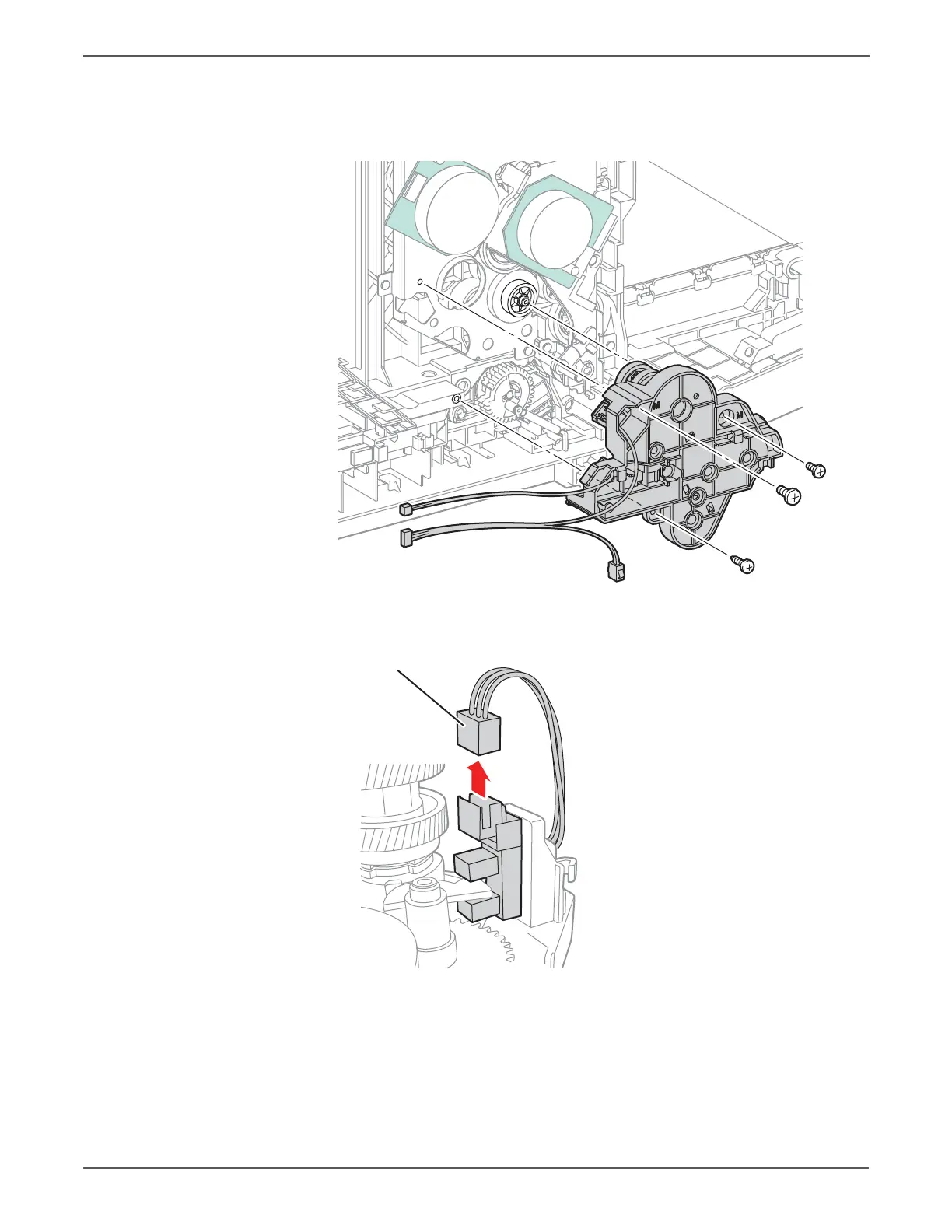
9. MFP Only: Unplug P/J261 from the Color Mode Sensor on the Feed Drive
Assembly, and release the harness from the hook on the Feed Drive Assembly.
The screw holes in the assembly are marked with “M” and “T” to indicate
where machine (M) or tapping (T) screws are used.
http://www.manuals4you.com

 Loading...