EasyManuals Logo

Xerox Phaser 6500 Service Manual

Xerox Phaser 6500
793 pages
To Next Page IconTo Next Page
To Previous Page IconTo Previous Page
Page #571 background imageLoading...
Page #571 background image
Phaser 6500/WorkCentre 6505 Service Manual Xerox Internal Use Only 8-123
Service Parts Disassembly
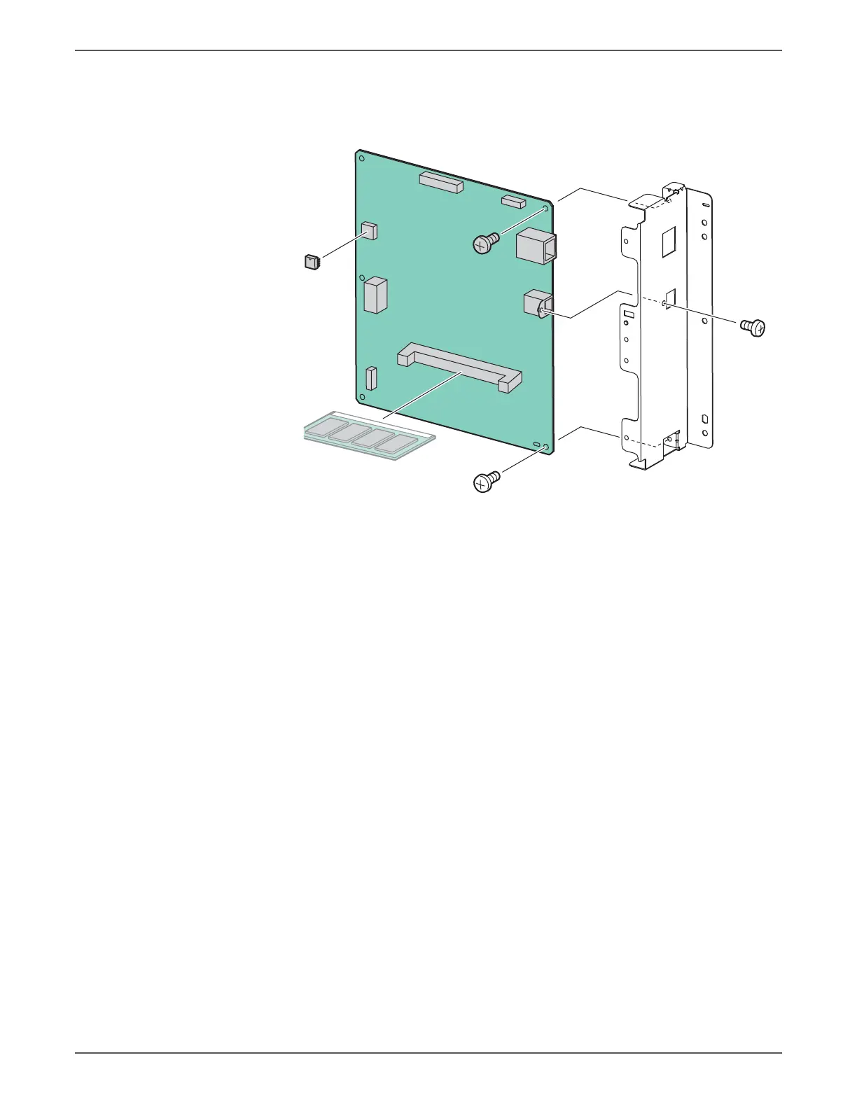
14. Remove the screw (silver, 4mm) that secures the USB connector on the Image
Processor Board to the I/O Plate.
15. Remove two screws (silver, 6mm) that secure the IP Board to the rear panel
and separate the two pieces.
Replacement Note
When installing a new IP Board, move the NVRAM and, if installed, the
Memory Card from the old IP Board to the new IP Board. Note NVRAM chip
orientation in the socket when removing and replacing the device
s6500-307

Table of Contents

Other manuals for Xerox Phaser 6500

Questions and Answers:

Question and Answer IconNeed help?

Do you have a question about the Xerox Phaser 6500 and is the answer not in the manual?

Xerox Phaser 6500 Specifications

General IconGeneral
Monthly Duty CycleUp to 40, 000 pages
Duplex PrintingManual
Print TechnologyLaser
Maximum Print Resolution600 x 600 x 4 dpi
First Page Out TimeAs fast as 12 seconds
ConnectivityUSB 2.0, Ethernet
Paper Capacity250 sheets + 1 sheet bypass tray
Supported Operating SystemsWindows, Mac OS, Linux
Print SpeedUp to 24 ppm (color) / Up to 24 ppm (black)

Related product manuals