April 2017
2-85
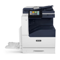
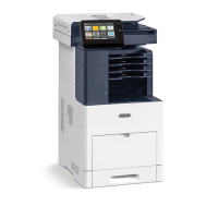
Xerox® VersaLink® B7025/B7030/B7035 Multifunction Printer
012-212, 012-213
Status Indicator RAPs
Launch Issue
Measure the voltage between P/J8988 pin 20 on the finisher PWB and ground. Actuate
the stacker height sensor 2.
The voltage changes.
YN
Install a new stacker height sensor 2, PL 13.27 Item 16.
Install a new finisher PWB, PL 13.45 Item 2.
Enter dC330 code 012-263. Manually rotate the encoder, PL 13.15 Item 19 to actuate the
stacker encoder sensor.
The display changes.
YN
Check the wiring between J8875 pin 2 and P/J8988 pin 23 for an open or short circuit, or
a loose or damaged connector.
The wiring is good.
YN
Reconnect or repair as necessary.
Measure the voltage between P/J8988 pins 22 and 24 on the finisher PWB. The voltage
is approximately +5VDC.
YN
Install a new finisher PWB, PL 13.45 Item 2.
Measure the voltage between P/J8988 pin 23 on the finisher PWB and ground. Manually
rotate the encoder, PL 13.15 Item 19 to actuate the stacker encoder sensor.
The voltage
changes.
YN
Install a new stacker encoder sensor, PL 13.15 Item 32.
Install a new finisher PWB, PL 13.45 Item 2.
Enter dC330 code 012-262. Actuate the stacker paper sensor, PL 13.15 Item 32. The dis-
play changes.
YN
Check the wiring between J8872 pin 2 and P/J8988 pin 14 for an open or short circuit, or
a loose or damaged connector.
The wiring is good.
YN
Reconnect or repair as necessary.
Measure the voltage between P/J8988 pins 13 and 15 on the finisher PWB. The voltage
is approximately +5VDC.
YN
Install a new finisher PWB, PL 13.45 Item 2.
Measure the voltage between P/J8988 pin 14 on the finisher PWB and ground. Actuate
the stacker no paper sensor
The voltage changes.
YN
Install a new stacker no paper sensor, PL 13.15 Item 32.
Install a new finisher PWB, PL 13.45 Item 2.
Install a new finisher PWB, PL 13.45 Item 2.
012-213 Stacker Tray Lower Limit Failure RAP
BSD-ON: BSD 13.15 Office Finisher LX Stacker Tray Control
012-213 Stacker descended lower than normal levels, below low limit height.
Initial Actions
• Check for obstructions under the tray.
• Check the operation of the stacker height sensor, PL 13.27 actuators.
• Check the tray raise/lower mechanism for damage or contamination.
Procedure
Enter dC330 code 012-264. Actuate the stacker height sensor 1. The display changes.
YN
Check the wiring between J8873 pin 2 and P/J8988 pin 17 for an open or short circuit, or
a loose or damaged connector.
The wiring is good.
YN
Reconnect or repair as necessary.
Measure the voltage between P/J8988 pins 16 and 18 on the finisher PWB. The voltage
is approximately +5VDC.
YN
Install a new finisher PWB, PL 13.45 Item 2.
Measure the voltage between P/J8988 pin 17 on the finisher PWB and ground. Actuate
the stacker height sensor 1.
The voltage changes.
YN
Install a new stacker height sensor 1, PL 13.27 Item 16.
Install a new finisher PWB, PL 13.45 Item 2.
Enter dC330 code 012-265. Actuate the stacker height sensor 2. The display changes.
YN
Check the wiring between J8874 pin 2 and P/J8988 pin 20 for an open or short circuit, or
a loose or damaged connector.
The wiring is good.
YN
Reconnect or repair as necessary.
Measure the voltage between P/J8988 pins 19 and 21 on the finisher PWB. The voltage
is approximately +5VDC.
YN
Install a new finisher PWB, PL 13.45 Item 2.
Measure the voltage between P/J8988 pin 20 on the finisher PWB and ground. Actuate
the stacker height sensor 2.
The voltage changes.
YN
Install a new stacker height sensor 2, PL 13.27 Item 16.
Install a new finisher PWB, PL 13.45 Item 2.
A B
A

 Loading...


