April 2017
8-37
Xerox® VersaLink® B7025/B7030/B7035 Multifunction Printer
Product Technical Overview
Launch Issue
High Capacity Feeder: Loading and Size Sensing
When the HCF tray is pulled out to load paper, the lift gear is separated from the drive gear and
the tray is free to fall to the bottom position. A torque limiter on the lift shaft slows the fall of the
paper tray to prevent damage to feeder components.
Size sensing is determined by the HCF size sensor (A) and the HCF size sensor (B). The
paper tray guides actuate the size sensors, Figure 21 and Table 1.
Figure 21 HCF tray in and paper size sensors
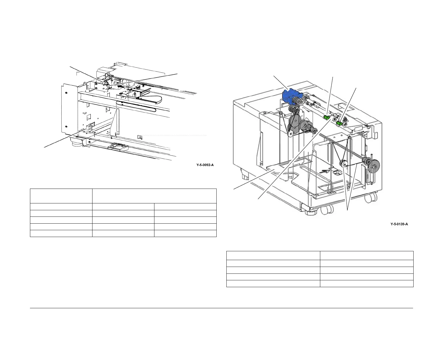
High Capacity Feeder: Tray Lift Operation
When the HCF tray is pushed in and actuates the HCF tray in sensor, Figure 21, the following
sequence of events occurs, refer to Figure 22:
1. The nudger roll is lowered.
2. The HCF feed/lift motor switches on and rotates CCW to lift the tray through a pulley and
cable arrangement.
3. Lift continues until the paper stack reaches and lifts the nudger roll, deactuating the HCF
level sensor.
4. The HCF feed/lift motor switches off.
High Capacity Feeder: Remaining Paper Calculation
The control logic calculates the amount of paper that remains in the HCF tray by the time it
takes for the paper stack to deactuate the HCF level sensor, Figure 22. The value is then dis
-
played on the UI for operator information. Refer to Table 2 for the time/quantity relationship.
If the HCF is empty, the HCF no paper sensor will actuate, and a Tray Empty message will dis-
play, Figure 22.
Figure 22 HCF level sensor
Table 1 Paper size by sensor state
Paper Size
Tray Paper Size Sensor
Sensor B Sensor A
B5 LEF or 7.25x10.5 inch LEF OFF OFF
8.5x11 inch LEF OFF ON
A4 LEF ON OFF
Long A4 (Irregular Settings) OFF OFF
HCF size senso
A, (letter)
HCF size sensor
B, (A4)
HCF tray in sensor
Table 2 Time/quantity relationship
Paper Remaining Lift Time (msec)
25% 8798-11526
50% 6068-8797
75% 3338-6067
FULL 0-3337
HCF level sensor
HCF no paper sensor
Nudger roll
HCF feed/lift motor
Tray
Pulley and cable

 Loading...