MPC5553/MPC5554 Microcontroller Reference Manual, Rev. 5
14-14 Freescale Semiconductor
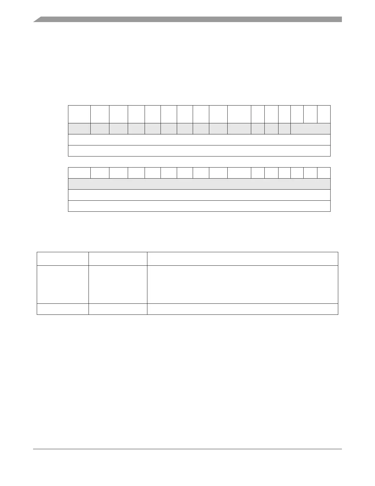
14.3.4.2.2 Ethernet Interrupt Mask Register (EIMR)
The EIMR register controls which interrupt events are allowed to generate actual interrupts. All
implemented bits in this CSR are read/write. This register is cleared upon a hardware reset. If the
corresponding bits in both the EIR and EIMR registers are set, the interrupt will be signalled to the CPU.
The interrupt signal will remain asserted until a 1 is written to the EIR bit (write 1 to clear) or a 0 is written
to the EIMR bit.
Figure 14-4. Interrupt Mask Register (EIMR)
14.3.4.2.3 Receive Descriptor Active Register (RDAR)
RDAR is a command register, written by the user, that indicates that the receive descriptor ring has been
updated (empty receive buffers have been produced by the driver with the empty bit set).
Whenever the register is written, the R_DES_ACTIVE bit is set. This is independent of the data actually
written by the user. When set, the FEC will poll the receive descriptor ring and process receive frames
(provided ECR[ETHER_EN] is also set). After the FEC polls a receive descriptor whose empty bit is not
set, then the FEC will clear R_DES_ACTIVE and cease receive descriptor ring polling until the user sets
the bit again, signifying that additional descriptors have been placed into the receive descriptor ring.
The RDAR register is cleared at reset and when ECR[ETHER_EN] is cleared.
0 1 2 3 4 5 6 7 8 9 101112131415
R HBERR
M
BABR
M
BABT
M
GRA
M
TXF
M
TXB
M
RXF
M
RXB
M
MII
M
EBERR
M
LC
M
RL
M
UN
M
000
W w1c w1c w1c w1c w1c w1c w1c w1c w1c w1c w1c w1c w1c
Reset0 0 0 0 0 0 0 0 0 0 000000
Address Base + 0x0008
16 17 18 19 20 21 22 23 24 25 26 27 28 29 30 31
R0 0 0 0 0 0 0 0 0 0 000000
W
Reset0 0 0 0 0 0 0 0 0 0 000000
Address Base + 0x0008
1
“w1c” signifies the bit is cleared by writing 1 to it.
Table 14-6. EIMR Field Descriptions
Bits Name Description
0-12 See Figure 17-6 and
Ta bl e 1 4- 5.
Interrupt mask. Each bit corresponds to an interrupt source defined by the EIR
register. The corresponding EIMR bit determines whether an interrupt
condition can generate an interrupt.
0 The corresponding interrupt source is masked.
1 The corresponding interrupt source is not masked.
13-31 — Reserved, should be cleared.