214733 155 Revision A
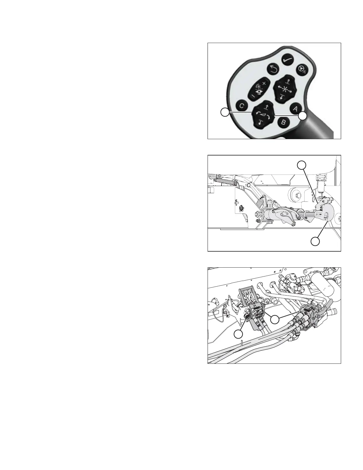
Figure 4.89: GSL
9. Activate HEADER TILT UP (A) and HEADER TILT DOWN (B)
cylinder switches on GSL to release the load on center-link
cylinder.
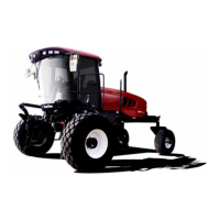
Figure 4.90: Hydraulic Center-Link
10. Stop the engine and remove the key.
11. Lift hook release (A) and lift hook (B) off header pin.
NOTE:
If optional center-link self-alignment kit is installed, lift
release (A) and then operate the link lift cylinder with the
REEL UP switch on the GSL to disengage the center-link
from the header.
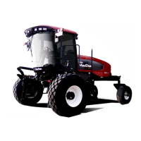
Figure 4.91: Header Drive Hydraulics
12. Disconnect header drive hydraulics (A) and electrical
harness (B) from the windrower.
OPERATION


 To Next Page