OPERATION
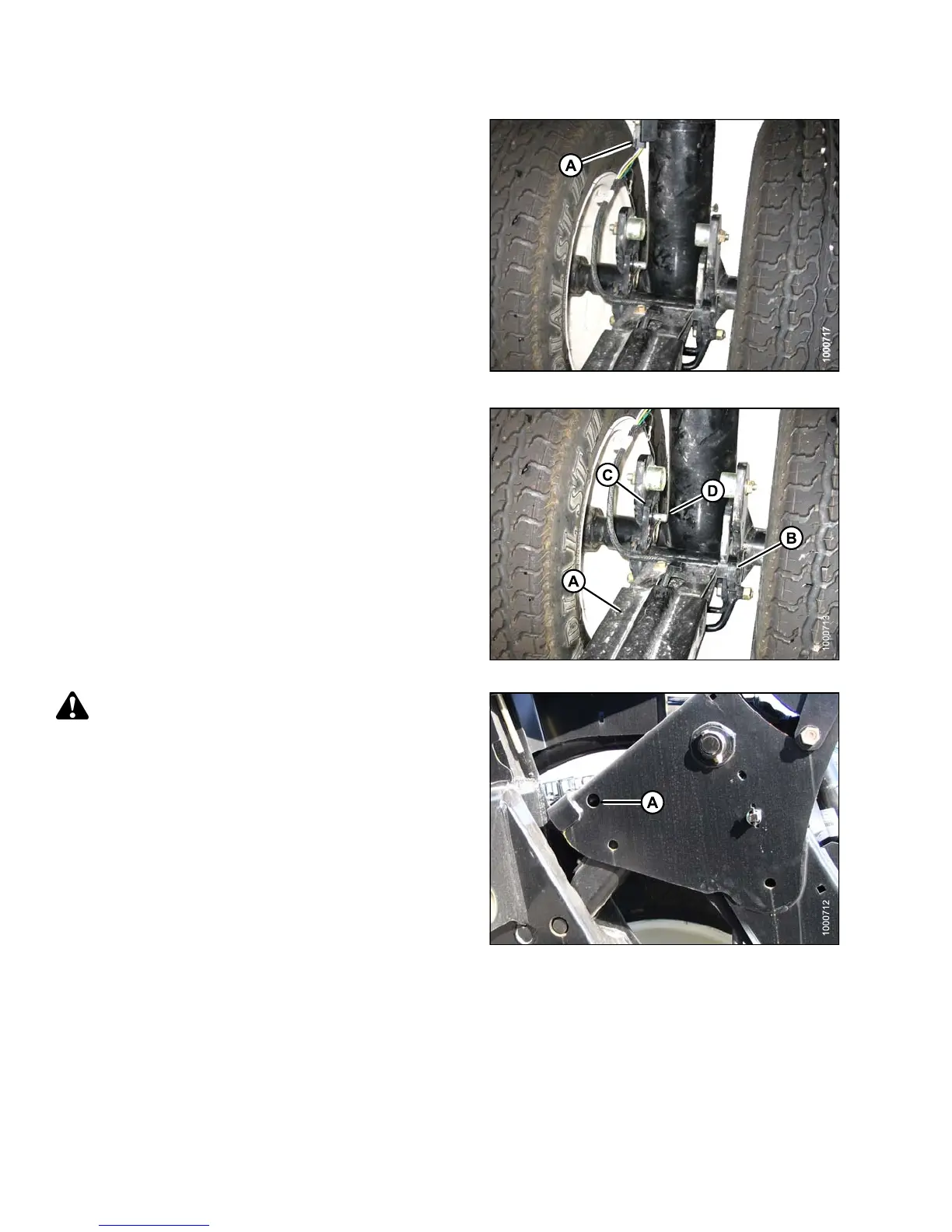
3. Disconnect wiring connector (A) at front wheel.
Figure 4.46: Header Transport Wheel
4. Remove clevis pin (D).
5. Push latch (C) and lift tow-bar (A) from hook. Release
latch and repla ce clevis pin.
6. Unhook tow-bar from w eight box.
Figure 4.47: Header Transport Wheel
CAUTION
Check to be sure a ll bystanders have cleared the area.
7. Start e ngine and low er lift arms until rear of lift a rms
floats up and away from the lift arm mechanism.
8. Stop engine and remove key from ignition.
9. Remove temporary lift pins (A) from weight box and
install pins ( F ) into holes a t rear of lift arms.
10. Start engine and fully raise lift arms. Stop engine and
remove key from ignition.
11. Engage lift cylinder safety props. Refer to 4.4.1 Header
Safety Props, page 193.
Figure 4.48: Lift Arms
147649 182 Revision A