OPERATION
12. M ove float pins from w orking hole location (A) to
disengage the float and store pins at storage hole
location (B).
IMPORTAN T:
To prevent damage to the lift system w hen lowering
header lift linkages without a header or weight box
attached to windrower, ensure that float engagement
pin is installed in storage hole location and NOT
installed in wo rking hole location.
Figure 4.49: Float P ins
13. Remove pins (A) securing lift linkages to w eight box
and retain pins for attaching header to windrower.
Disengage lift cylinder safety props. Refer to 4.4.1
Header Safety Props, page 193.
Figure 4.50: Weight Box
14. Start engine, lower weight box onto blocks, and
back away.
15. Attach header to windrower. Refer to 4.5 Attaching and
Detaching Headers, page 213.
16. Convert header into field position. Refer to header
operator’s manual for procedure.
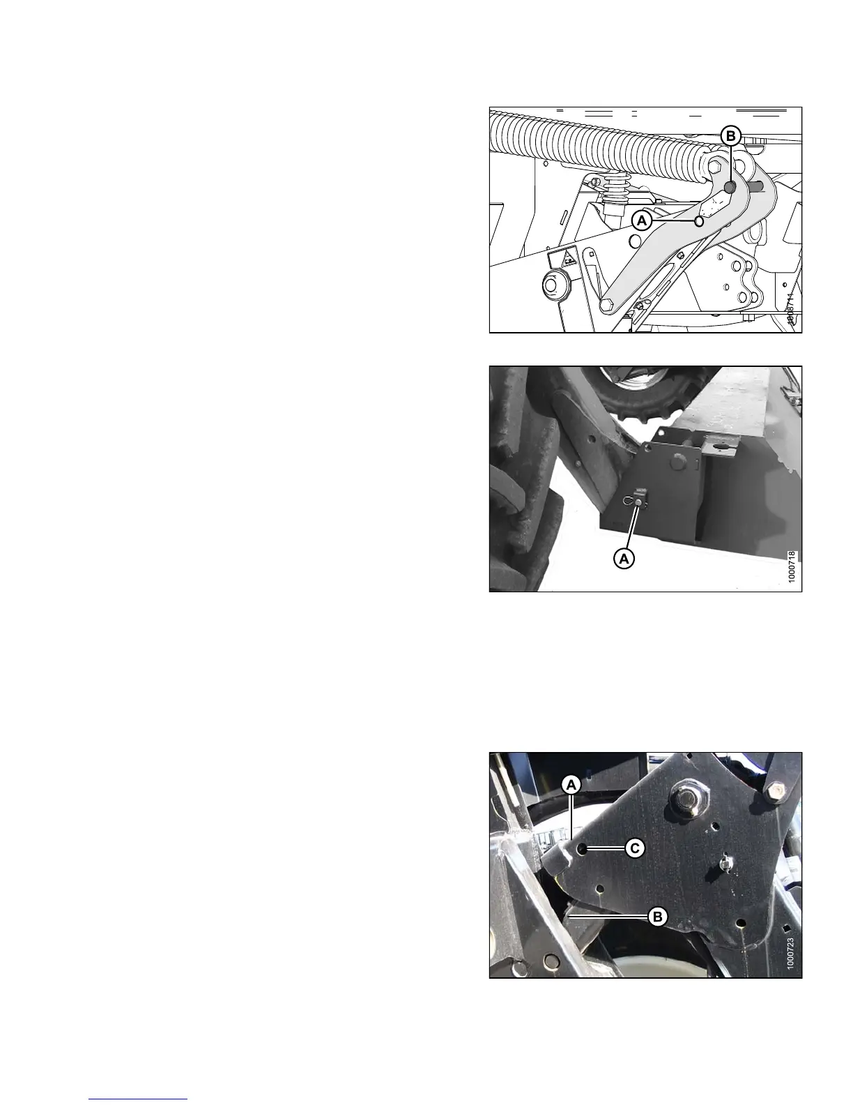
17. Start engine
and lower header to ground. Continue to
retract lift
cylinders so that member (A) lifts off of link (B)
18. Remove tempo
rary lift pins (C) from lift arms and install
pins into sto
rage holes in weight box.
19. Before oper
ating the machine, double check that
all pins are
secure and that all safety equipment is
installed a
nd fully functional.
20. Proceed wit
h operation of header.
Figure 4.51: Lift Arms
147649 183 Revision A