OPERATION
9. Drive windrower so that windrower lift arms are
positioned into the weight box pockets.
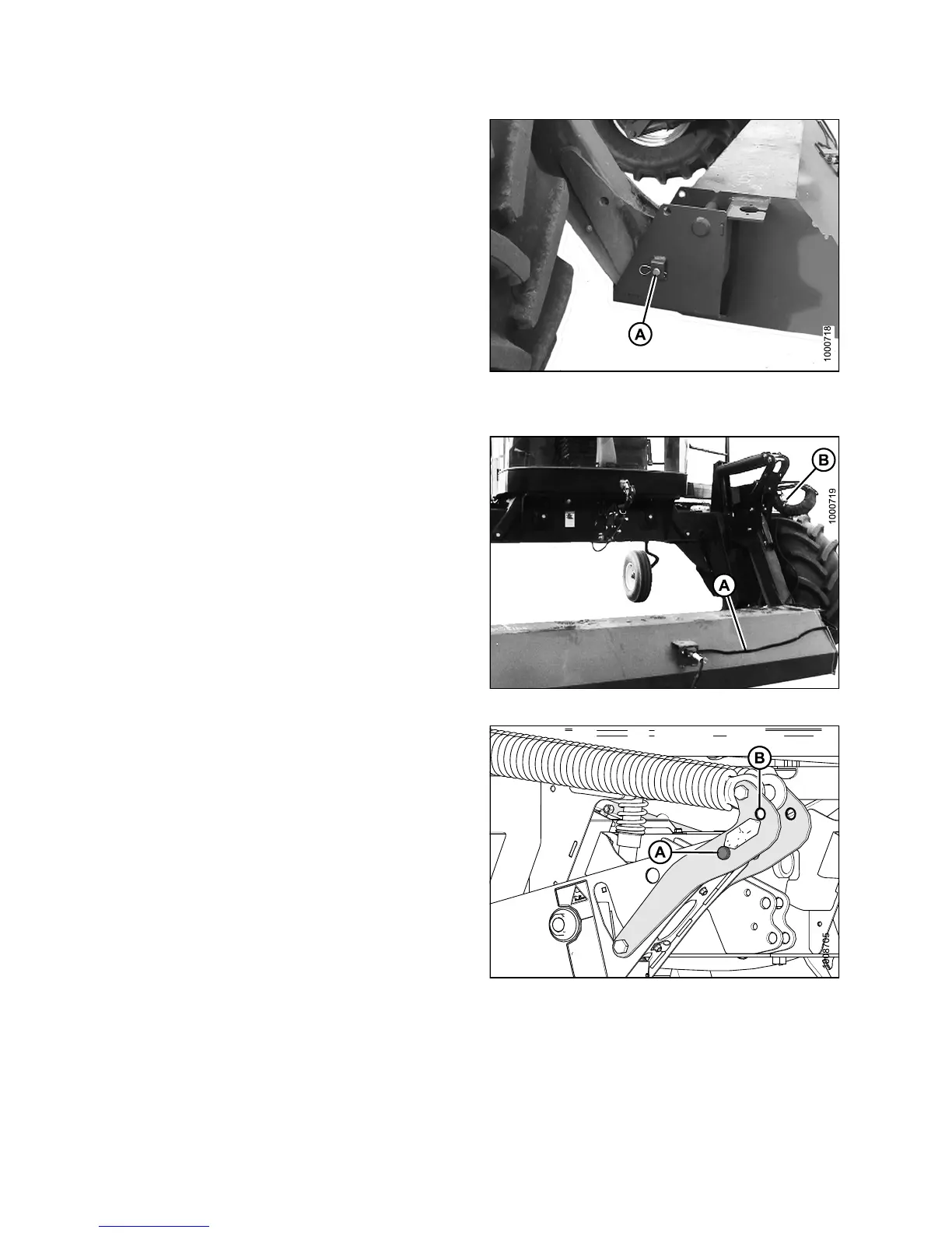
10. Raise lift arms slightly, install lo cking pins (A) into
pockets, and through windrower header lift linkages.
Secure with hairpin.
NOTE:
Pins (A) were previously r emoved from the
header lift linka ge lower end.
Figure 4.58: Windrower Lift Linkage
11. Route the weight box harness (A) to the electrical
connector at the left side lift linkage and connect
harness to connector on windrower (B).
12. Raise lift arms fully, shut engine OFF, and remove key
from ignition.
Figure 4.59: Weight Box
13. Move float pins from storage location (A) to engaged
position (B).
Figure 4.60: Lift Linkage
147649 186 Revision A