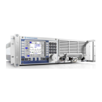
M3SR Series 4100 Menu PMU (3031)
3.64 Operating Manual 6175.4760.02 – 01
3.4.2 Menu PMU (3031)
In an HF-Broadband system (HF-BB) it is possible to control up to four R&S VK4190 Power
Amplifiers from one R&S GX4100 Receiver / Exciter. The Power Management Unit (PMU),
built into the R&S GV4190, allows to connect up to three additional R&S GX4100 and up to
four R&S VK4190 to produce an output power of 1 kW, 2 kW or 4 kW. The different possibil-
ities to achieve these output powers are called "Mode". Each mode has a two-digit name of
the form xy.
The R&S GX4100 and R&S VK4190 in an HF-BB system get shortened names. GX2 means
R&S GX4100 connected to port 2 of the PMU, GX1 is the receiver / exciter unit of the R&S
GV4190.
In 1kW and 2kW modes
• x describes how GX1 and GX2 are connected to VK1 and VK2 (first group)
• y describes how GX3 and GX4 are connected to VK3 and VK4 (second group).
In 4 kW modes
• x describes the R&S GX4100 which controls, and coherently drives, all four R&S
VK4190
•y is always “3”.
Description of x, y values in 1 kW and 2 kW modes
0 1 kW mode: Each GX controls the VK with the same port number.
1 2 kW mode: The first GX (GX1 / GX3) of a group controls, and coherently drives, both amplifiers
of its group.
2 2 kW mode: The second GX (GX2 / GX4) of a group controls, and coherently drives, both amplifi-
ers of its group.

 Loading...