M3SR Series 4100 Menu PMU (3031)
3.66 Operating Manual 6175.4760.02 – 01
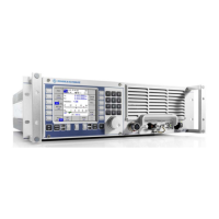
Figure 3.38 Menu 3031: PMU, e.g. 4 kW System
The central area of the menu PMU shows a graphical representation of the HF-BB system.
The green area marks the R&S GV4190. The receiver / exciter functionality and the PMU are
shown as two logical devices. The receiver / exciter is shown as GX1, the rectangular box
above represents the PMU. Black lines in the PMU box show the HF and control connections
between the different R&S GX4100 and R&S VK4190. These are also shown as rectangular
boxes.
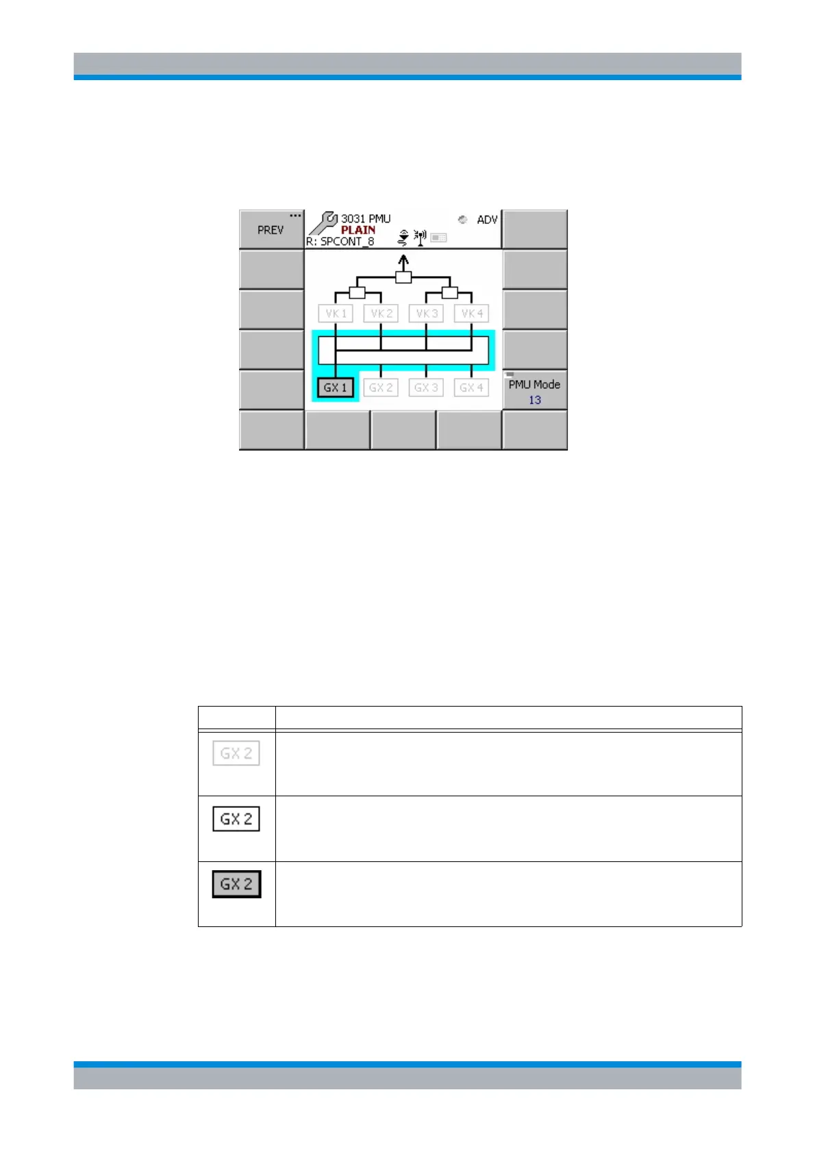
Symbol Description
There is no R&S GX4100 connected to port 2.
There is a R&S GX4100 connected to the port 2.
The R&S GB4000C is connected to the R&S GX4100 which is connected to port 2.
ICN-4D-G-231000-R-D0894-02200-A-01-1
 Loading...