Operating Manual 6175.4760.02 – 01 2.7
M3SR Series 4100 Rear Cabling
Necessary cabling at the rear side:
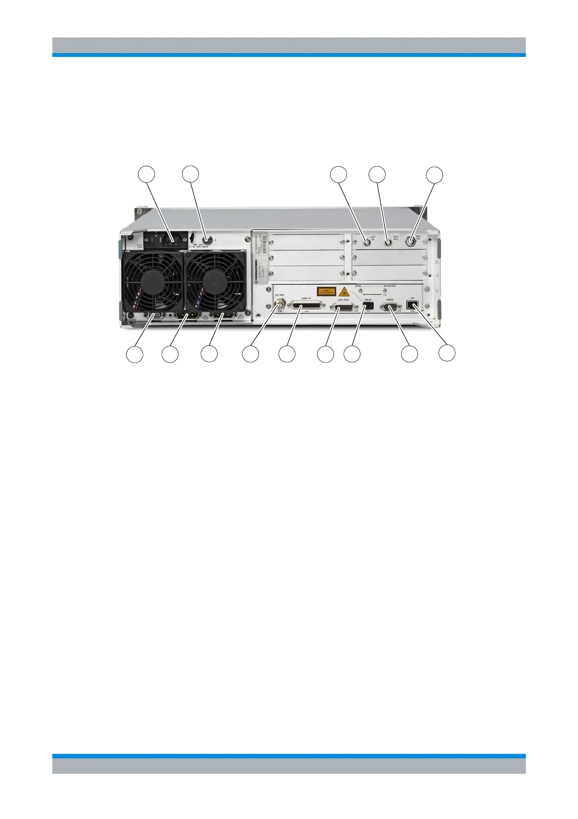
Figure 2.2 Rear Connectors of Receiver
1 Mains Connector X1
2 Ground Connector
3 Rx Antenna Connector X2111
4 not used in this application
5 GPS Antenna Connector X2113
6 LAN Connector X20
7 REMOTE Connector X24
8 RCB SER Connector X21(control)
9 DATA/RS232 Connector X23
10 AUDIO/PTT Connector X26
11 EXT SYNC Connector X10
12 not used in this application
13 Connector X32 (BATTERY) to external battery
14 not used in this application
In case of a power supply failure the system switches automatically to a 28 V DC battery sup-
ply which can be connected to X32.
ICN-4D-C-231000-R-D0894-02006-A-01-1
1
2
3
5
6
7
8
9
10
11
12
13
4
14
 Loading...