M3SR Series 4100
List of Figures
Operating Manual 6175.4760.02 – 01 13
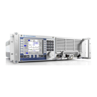
Figure 1.1 R&S M3SR Series 4100 Radio (Front View) ............................................................................. 1.2
Figure 1.2 R&S M3SR Series 4100 Radio, e.g. Transceiver (Top View without Cover, Example)............. 1.6
Figure 1.3 R&S IN4190 Power Supply ..................................................................................................... 1.11
Figure 1.4 R&S IN4000A Power Supply................................................................................................... 1.13
Figure 1.5 Radio with Built-In Control Unit................................................................................................ 1.16
Figure 1.6 Radio with Additional Remote Control Unit.............................................................................. 1.17
Figure 1.7 Radio with Built-In Control Unit and with two Remote Control Units ....................................... 1.19
Figure 1.8 Several Radios and Remote Control Units in a Network (Example)........................................ 1.21
Figure 2.1 Installation into a 19" Rack, Example ........................................................................................ 2.4
Figure 2.2 Rear Connectors of Receiver .................................................................................................... 2.7
Figure 2.3 Rear Connectors of Receiver / Exciter ...................................................................................... 2.9
Figure 2.4 Rear Connectors of Transceiver.............................................................................................. 2.11
Figure 2.5 Rear Connectors of Power Management Unit......................................................................... 2.13
Figure 2.6 Front Cabling ........................................................................................................................... 2.15
Figure 2.7 Cabling between R&S GX4100A/D, R&S VK4190 and R&S IN4190 ...................................... 2.17
Figure 2.8 System Cabling for Transceiver .............................................................................................. 2.20
Figure 2.9 Switching the Radio On ........................................................................................................... 2.23
Figure 2.10 Switching the Radio with Built-In Control Unit On.................................................................... 2.24
Figure 2.11 Example for the Automatic Update Process of a Frontend...................................................... 2.28
Figure 2.12 Switching the Radio Off ........................................................................................................... 2.30
Figure 2.13 Switching the Radio with Built-In Control Unit Off....................................................................2.31
Figure 2.14 Radio IP Settings (Example) ................................................................................................... 2.35
Figure 2.15 Changing Radio IP Settings Using the upd32.exe Tool .......................................................... 2.36
Figure 2.16 Upd32: Select 'LAN Settings via Ethernet'............................................................................... 2.38
Figure 2.17 Upd32: Select Targets for Ethernet Communication Dialog (Example)................................... 2.38
Figure 2.18 Upd32: LAN Setting Dialog (Example) .................................................................................... 2.39
Figure 2.19 Upd32: Finish the Update........................................................................................................ 2.39
Figure 2.20 Control Unit IP Settings ........................................................................................................... 2.42
Figure 2.21 Radio IP Address List of Control Unit ...................................................................................... 2.43
Figure 2.22 Example Configuration ............................................................................................................ 2.44
Figure 3.1 Radio with Local Control Unit .................................................................................................... 3.1
Figure 3.2 Radio Backplane with Interfaces ............................................................................................... 3.2
Figure 3.3 Radio and Remote Control Unit Connected via LAN................................................................. 3.3
Figure 3.4 Front Panel ................................................................................................................................ 3.6
Figure 3.5 Control Elements of R&S GB4000C Control Unit.................................................................... 3.10
Figure 3.6 Menu Page Design (Example)................................................................................................. 3.12

 Loading...