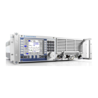
M3SR Series 4100 System Cabling
2.18 Operating Manual 6175.4760.02 – 01
1 Control Cable / Fiber Optic (receiver / exciter X21 – power amplifier X31), R&S GK4101,
6120.5607.xx (xx: 10 = 1.0 m, 35 = 3.5 m, 50 = 50 m)
2 DC Cable (receiver / exciter X31 – power amplifier X24), R&S GK4104, 6120.5907.xx
(05 = 0.5 m, 10 = 1.0 m, 25 = 2.5 m)
3 RF Cable (receiver / exciter X2112 – power amplifier X20)
R&S GK4105 6120.3604.03 (03 = 3 m)
4 Control Cable (power amplifier X23 – power supply X33)
R&S GK4106 6120.3656.03 (03 = 30 m)
5 DC Cable (power amplifier X21 – power supply X34)
R&S GK4107 6120.3704.03 (03 = 3 m)
6 Ground Connection (M6)
7 Antenna Tuning Unit Connection (Control)
R&S FK4190M / R&SFK2900M: R&S GK2903M 6117.9757.xx
R&S FK4150U: R&S GK2903 6117.9505.xx
(xx = 10, 20, 30, 40, 50, 60, 80 = 80 m, 99 = 100 m)
8 Antenna or Antenna Tuning Unit Connection (RF), Type N
9 Mains Connection
10 Battery Connection
For the connection of an R&S BV4190 Transformer 440 V to R&S IN4150 / R&S IN4190 (.03)
use a cable of the type R&S GK4108 6120.3756.03.
For further system cablings for receiver/exciter see sect. 9 Drawings.

 Loading...