MPC5553/MPC5554 Microcontroller Reference Manual, Rev. 5
12-32 Freescale Semiconductor
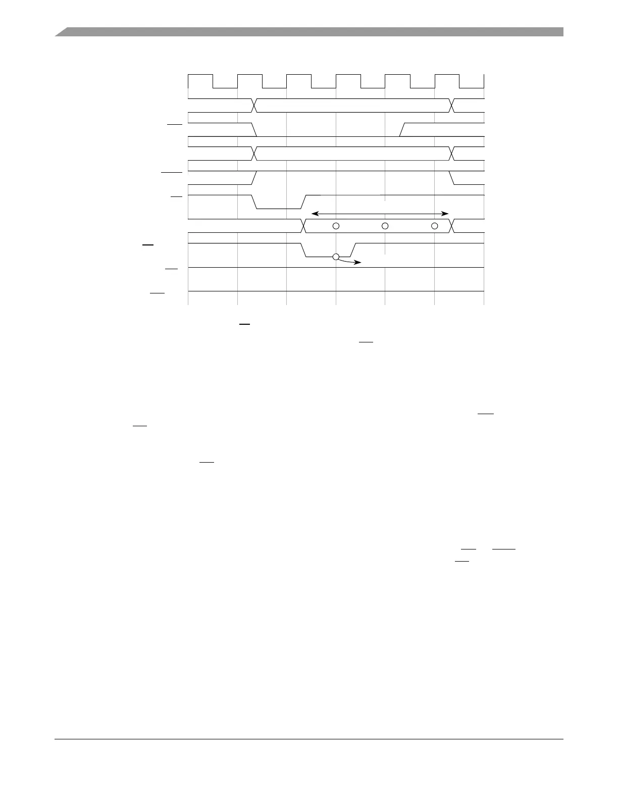
Figure 12-16. Single Beat 32-bit Write Cycle, Non-CS Access, Zero Wait States
12.4.2.4.3 Back-to-Back Accesses
Due to internal bus protocol, one dead cycle is necessary between back-to-back external bus accesses that
are not part of a set of small accesses (see Section 12.4.2.6, “Small Accesses (Small Port Size and Short
Burst Length)” for small access timing). A dead cycle refers to a cycle between the TA of a previous
transfer and the TS of the next transfer.
NOTE
In some cases, CS remains asserted during this dead cycle, such as the cases
of back-to-back writes or read-after-write to the same chip-select. See
Figure 12-20 and Figure 12-21.
Besides this dead cycle, in most cases, back-to-back accesses on the external bus do not cause any change
in the timing from that shown in the previous diagrams, and the two transactions are independent of each
other. The only exceptions to this are as follows:
• Back-to-back accesses where the first access ends with an externally-driven TA
or TEA. In these
cases, an extra cycle is required between the end of the first access and the TS assertion of the
second access. See Section 12.4.2.9, “Termination Signals Protocol,” for more details.
Figure 12-17, Figure 12-18, and Figure 12-19 show a few examples of back-to-back accesses on the
external bus.
DATA is valid
CLKOUT
ADDR[8:31]
TS
DATA[0:31]
TA
(Input)
RD_WR
TSIZ[0:1]
BDIP
WE[0:3]
CS
x
00
DATA is valid
The EBI drives address and control signals an extra cycle because it uses a latched
version of the external TA
(1 cycle delayed) to terminate the cycle.
*
*