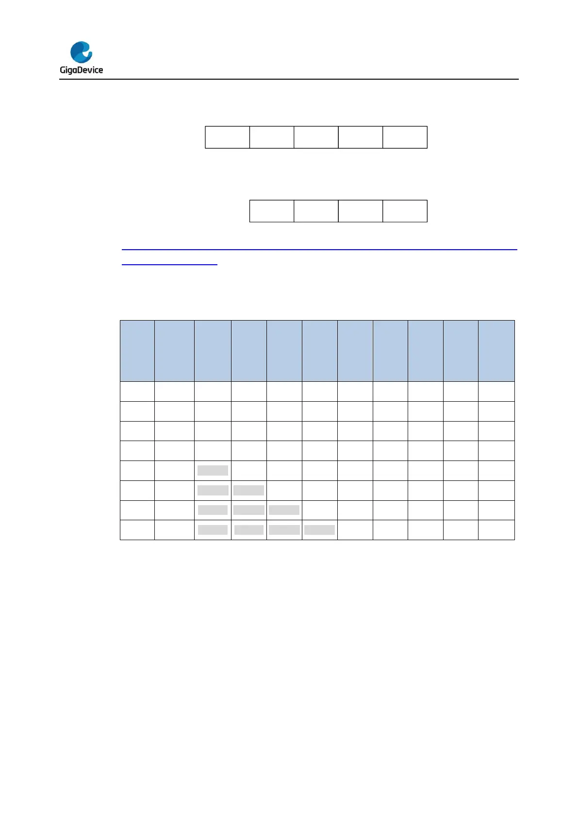
Table 11-5. Maximum output results for N and M combimations (grayed values
indicates truncation) gives the data format for the various N and M combination, for a raw
conversion data equal to 0xFFF.
Table 11-5. Maximum output results for N and M combimations (grayed values
indicates truncation)
When compared to standard conversion mode, the conversion timings of oversampling
mode do not change, and the sampling time remains equal throughout the oversampling
sequence. New data is supplied every N conversions, and the equivalent delay is equal to:
N x t
ADC
= N x (t
SMPL
+ t
CONV
) (11-2)
Oversampling work with ADC modes
Most of the ADC work modes are available when oversampling is enabled.
Routine sequence.
ADC started by software or external triggers.
Single or scan, continuous or discontinuous operation modes.
Programmable sample time.
Analog watchdog.
 Loading...

