GD32F3x0 User Manual
129
The schmitt trigger input is de-activated.
Read access to the port input status register gets the value “0”.
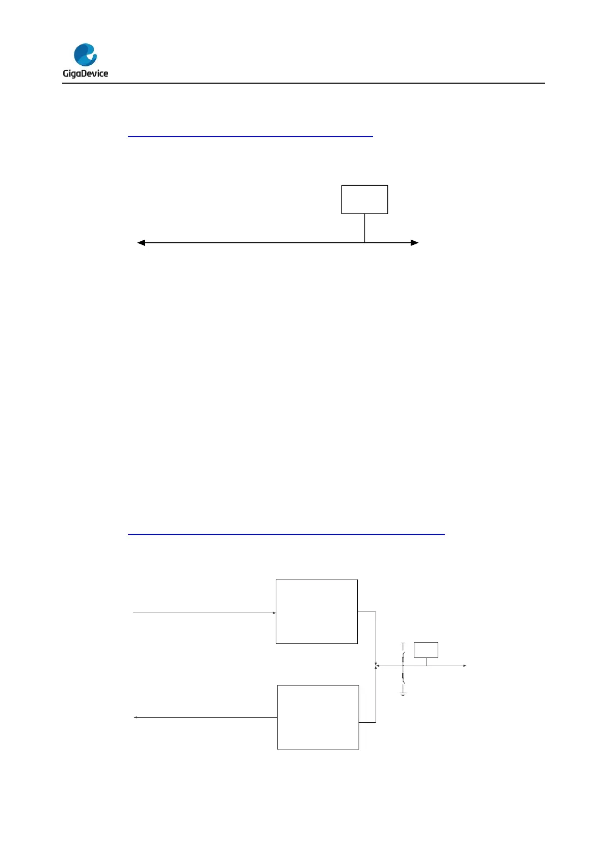
Figure 7-4. Basic structure of Analog configuration shows the analog configuration of the
GPIO pin.
Figure 7-4. Basic structure of Analog configuration
7.3.7. Alternate function (AF) configuration
To suit for different device packages, the GPIO supports some alternate functions to some
other pins by software.
When be configured as Alternate Function:
The output buffer is turned on in Open-Drain or Push-Pull configuration.
The output buffer is driven by the peripheral.
The schmitt trigger input is activated.
The weak pull-up and pull-down resistors could be chosen.
The data present on the I/O pin is sampled into the port input status register every AHB
clock cycle.
A read access to the port input status register gets the I/O state in Open-Drain mode.
A read access to the port output control register gets the last written value in Push-Pull
mode.
Figure 7-5. Basic structure of Alternate function configuration shows the alternate
function configuration of the GPIO pin.
Figure 7-5. Basic structure of Alternate function configuration