GD32F3x0 User Manual
417
counter. However, there exist several clock delays to perform the comparison result between
the counter value and the TIMERx_CHxCV value. In order to reduce the delay to a minimum
value, the user can set the CHxCOMFEN bit in each TIMERx_CHCTL0 register. After a
trigger rising occurs in the single pulse mode, the OxCPRE signal will immediately be forced
to the state which the OxCPRE signal will change to, as the compare match event occurs
without taking the comparison result into account. The CHxCOMFEN bit is available only
when the output channel is configured to operate in the PWM0 or PWM1 output mode and
the trigger source is derived from the trigger signal.
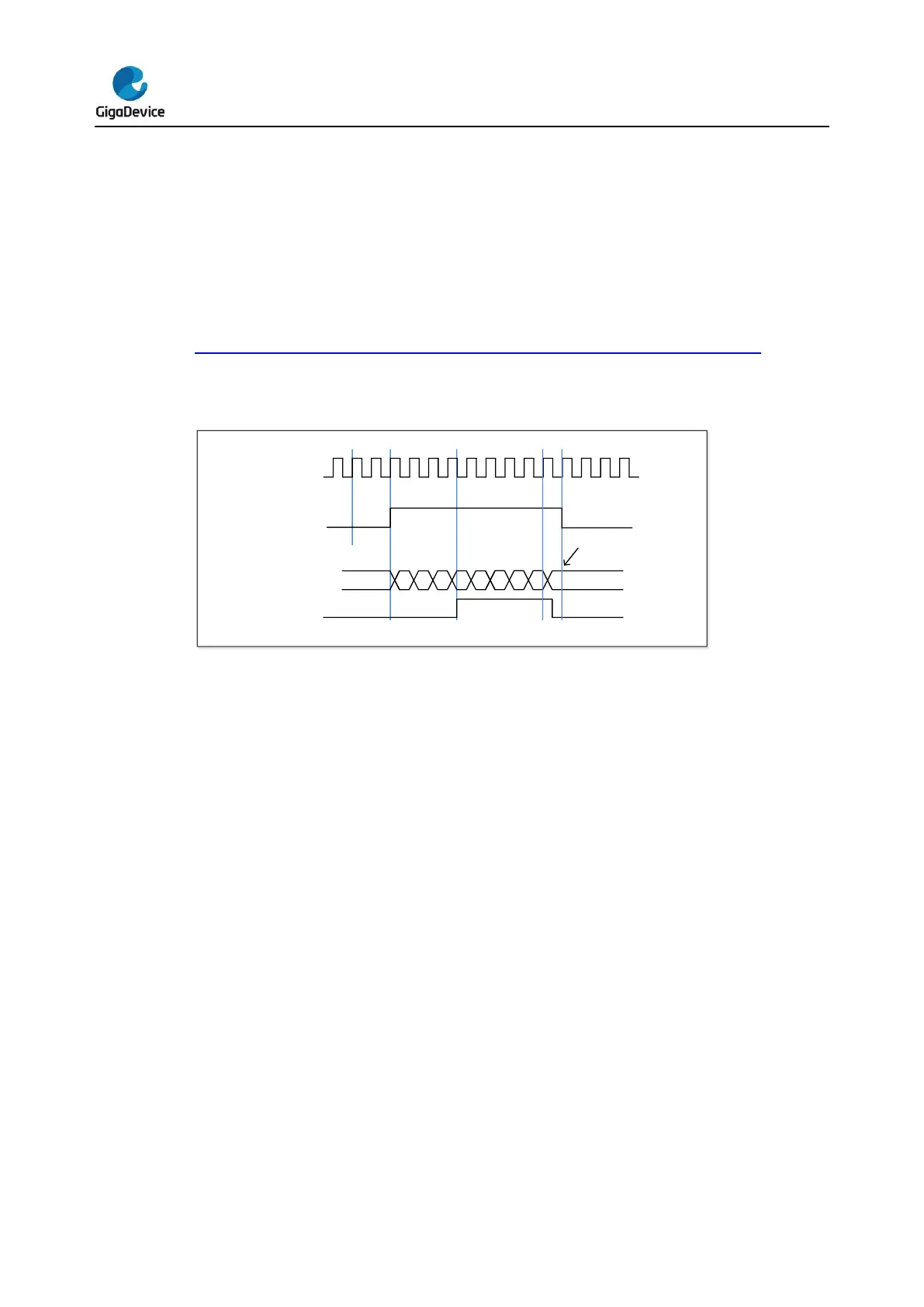
Figure 16-79. Single pulse mode TIMERx_CHxCV = 0x04 TIMERx_CAR=0x60 shows an
example.
Figure 16-79. Single pulse mode TIMERx_CHxCV = 0x04 TIMERx_CAR=0x60
Timer DMA mode
Timer’s DMA mode is the function that configures timer’s register by DMA module. The
relative registers are TIMERx_DMACFG and TIMERx_DMATB. Of course, you have to
enable a DMA request which will be asserted by some internal event. When the interrupt
event was asserted, TIMERx will send a request to DMA, which is configured to M2P mode
and PADDR is TIMERx_DMATB, then DMA will access the TIMERx_DMATB. In fact, register
TIMERx_DMATB is only a buffer; timer will map the TIMERx_DMATB to an internal register,
appointed by the field of DMATA in TIMERx_DMACFG. If the field of DMATC in
TIMERx_DMACFG is 0(1 transfer), then the timer’s DMA request is finished. While if
TIMERx_DMATC is not 0, such as 3(4 transfers), then timer will send 3 more requests to
DMA, and DMA will access timer’s registers DMATA+0x4, DMATA+0x8, DMATA+0xc at the
next 3 accesses to TIMERx_DMATB. In a word, one-time DMA internal interrupt event assert,
DMATC+1 times request will be send by TIMERx.
If one more time DMA request event coming, TIMERx will repeat the process as above.
Timer debug mode
When the Cortex
®
-M4 halted, and the TIMERx_HOLD configuration bit in DBG_CTL1
register set to 1, the TIMERx counter stops.
 Loading...

