GD32F3x0 User Manual
455
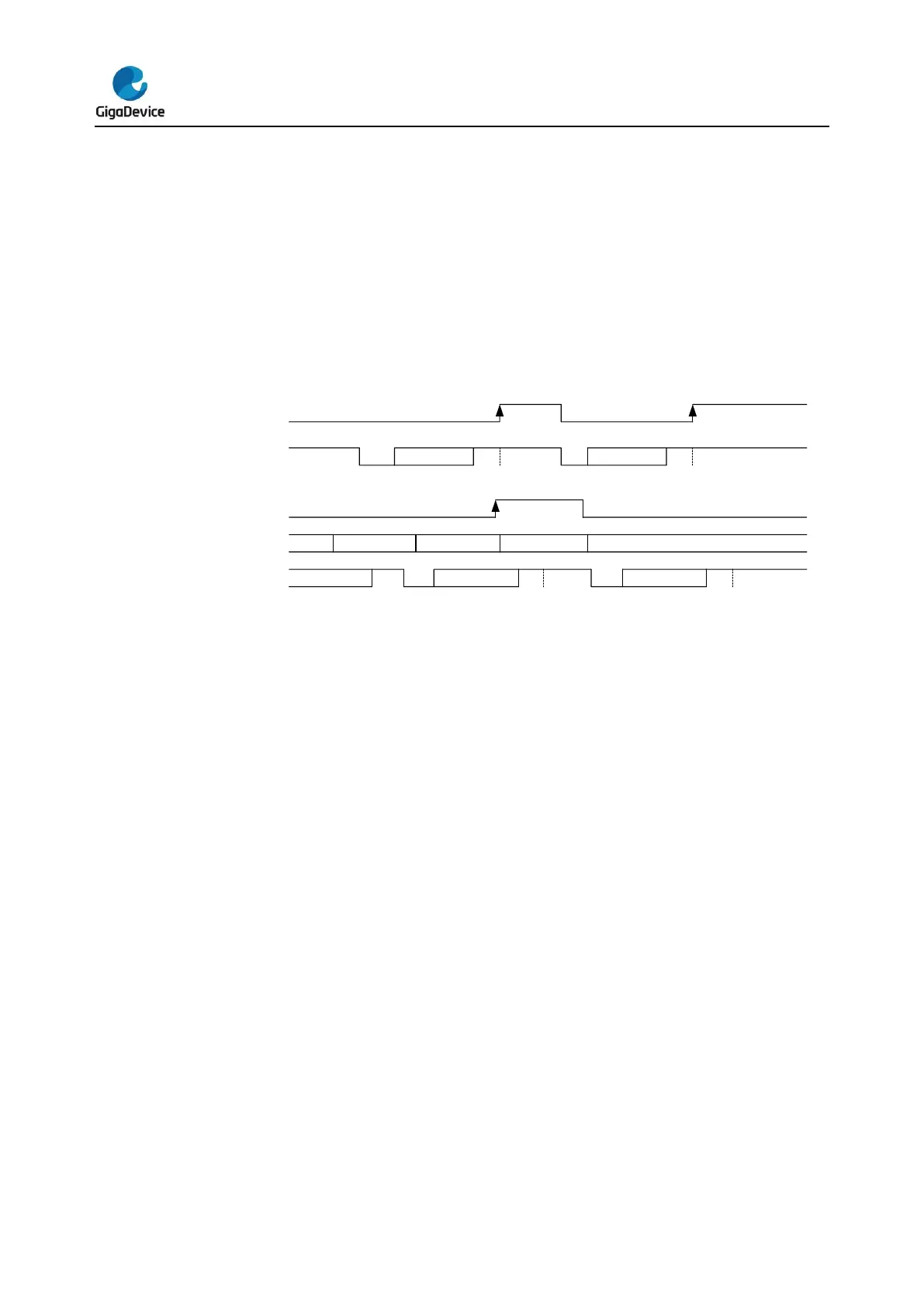
next frame. The nRTS signal keeps high when the receive buffer is full.
CTS flow control
The USART transmitter monitors the nCTS input pin to decide whether a data frame can be
transmitted. If the TBE bit in USART_STAT is ‘0’ and the nCTS signal is low, the transmitter
transmits the data frame. When the nCTS signal goes high during a transmission, the
transmitter stops after the current transmission is accomplished.
Figure 18-8. Hardware flow control
If the CTS flow control is enabled, when the nCTS signal is changed, the CTSF bit in
USART_STAT register will be set. If the CTSIE bit in USART_CTL2 register has been set, an
interrupt will be occurred.
RS485 Driver Enable
The driver enable feature, which is enabled by setting bit DEM in the USART_CTL2 control
register, allows the user to activate the external transceiver control, through the DE (Driver
Enable) signal. The assertion time, which is programmed using the DEA [4:0] bits field in the
USART_CTL0 control register, is the time between the activation of the DE signal and the
beginning of the START bit. The de-assertion time, which is programmed using the DED [4:0]
bits field in the USART_CTL0 control register, is the time between the end of the last stop bit
and the de-activation of the DE signal. The polarity of the DE signal can be configured using
the DEP bit in the USART_CTL2 control register.
18.3.7. Multi-processor communication
In multiprocessor communication, several USARTs are connected as a network. It will be a
big burden for a device to monitor all of the messages on the RX pin. To reduce the burden of
a device, software can put an USART module into a mute mode by writing 1 to the MMCMD
bit in USART_CMD register.
If a USART is in mute mode, all of the receive status bits cannot be set. The USART can also
be wake up by hardware by one of the two methods: idle frame method and address match
method.


 To Next Page