GD32F3x0 User Manual
255
will be generated. In addition, the update events will be generated after (TIMERx_CREP+1)
times of overflow events. The counting direction bit DIR in the TIMERx_CTL0 register should
be set to 0 for the up counting mode.
Whenever, if the update event software trigger is enabled by setting the UPG bit in the
TIMERx_SWEVG register, the counter value will be initialized to 0 and generates an update
event.
If set the UPDIS bit in TIMERx_CTL0 register, the update event is disabled.
When an update event occurs, all the shadow registers (repetition counter, counter auto
reload register, prescaler register) are updated.
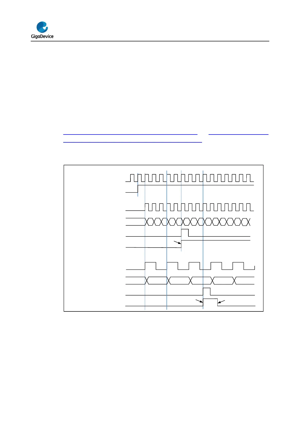
Figure 16-4. Timing chart of up counting mode, PSC=0/2 and Figure 16-5. Timing chart
of up counting mode, change TIMERx_CAR on the go show some examples of the
counter behavior for different clock prescaler factor when TIMERx_CAR=0x99.
Figure 16-4. Timing chart of up counting mode, PSC=0/2
 Loading...

